

Water Hole Spacer: The Definitive Technical Guide for Wet Borehole Air Decking in Mining and Quarry Blasting
1. Introduction to Water Hole Spacers
2. What Is a Water Hole Spacer?
3. The Challenge of Wet Boreholes in Blasting Operations
4. How Water Hole Spacers Work: Design Principles and Mechanisms
5. Key Advantages of Water Hole Spacers
6. Comparison with Dry Hole Spacers and Other Air Decking Technologies
7. Technical Specifications and Product Sizing
8. Applications Across Mining, Quarrying, and Civil Engineering
9. Installation and Operating Procedures for Wet Hole Conditions
10. Safety Protocols and Regulatory Compliance
11. Economic Analysis and Cost-Benefit Evaluation
12. Troubleshooting Common Wet Hole Spacer Issues
13. Frequently Asked Questions (FAQ)
14. Conclusion and Future Trends
In mining, quarrying, and civil construction blasting, water-filled boreholes represent one of the most persistent and challenging operational conditions. Whether caused by groundwater infiltration, seasonal rainfall, proximity to aquifers, or subaquatic drilling environments, water in blast holes complicates every aspect of the charging process—from explosive selection and placement to initiation reliability and overall blast performance. The water hole spacer (also known as a wet hole spacer, water-resistant blast hole spacer, or underwater borehole plug) has emerged as a critical technology specifically engineered to overcome these challenges, enabling effective air decking and optimized explosive energy distribution even in fully or partially submerged borehole conditions.
The presence of water in boreholes is not merely an inconvenience; it fundamentally alters the physics of explosive energy transmission, introduces hydrostatic forces that can displace or destabilize conventional spacers, and creates an environment where standard air decking techniques often fail. Water can desensitize certain explosive formulations, create buoyancy effects that float lightweight devices upward, wash drilling cuttings into seal zones to compromise inflatable plugs, and conduct shock waves in ways that modify fragmentation patterns. Without purpose-designed water hole spacers, operators are forced to either abandon wet holes (at significant cost in lost drilling investment), use continuous explosive columns that waste energy and increase costs, or rely on improvised solutions that compromise safety and blast quality.
This comprehensive guide examines the water hole spacer as a specialized category of blast hole accessory, distinct from general-purpose dry hole spacers and requiring unique design features, operational procedures, and safety considerations. Whether your operation encounters seasonal water in surface production holes, persistent groundwater in underground development faces, or fully submerged conditions in marine and riverbed blasting, this resource provides the technical depth and practical guidance needed to implement water hole spacer technology effectively.
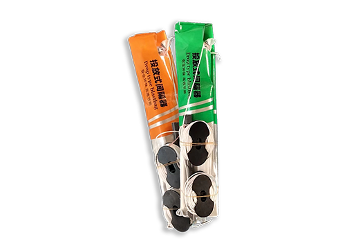
A water hole spacer is a specialized blast hole accessory designed to create a stable air deck—or physical barrier—within a water-filled or water-bearing borehole, separating segments of explosive charge while maintaining position against hydrostatic pressure, buoyancy forces, and dynamic water flow. Unlike standard dry hole spacers that assume minimal or no water presence, water hole spacers incorporate specific design features that address the unique physical and chemical challenges posed by submerged borehole environments.
The functional requirements of a water hole spacer extend beyond simple physical separation. An effective water hole spacer must simultaneously:
• Resist hydrostatic pressure: Maintain structural integrity and seal effectiveness against the static pressure of the water column above and below the spacer
• Overcome buoyancy: Remain at the designed depth despite the upward buoyant force exerted by displaced water on the spacer body
• Prevent water migration: Create a watertight seal that prevents water from flowing past the spacer to contact explosives or dilute air decks
• Accommodate water flow: Function reliably in boreholes with active water inflow, where water is entering the hole during the loading process
• Resist chemical degradation: Maintain material integrity when exposed to potentially corrosive groundwater, saline water, or chemically treated drilling fluids
• Enable controlled deployment: Allow operators to lower the spacer through a water column to a precise depth and verify its position before committing to explosive loading
Water hole spacers are manufactured in several technological categories, each optimized for specific wet hole conditions:
Spacer Category | Primary Mechanism | Water Resistance Level | Typical Application |
Inflatable water hole spacer | Gas-inflated bladder with hydrostatic-resistant seal | High, up to full submersion | Deep wet holes, variable diameter |
Weighted rigid water hole spacer | Dense material (metal, concrete, polymer) with sealing gasket | Moderate to high | Bottom decking, uniform diameter |
Sinking inflatable spacer | Ballasted bladder that sinks before inflation | High | Deep water columns, active inflow |
Water-displacement spacer | Expanding foam or chemical reaction displacing water | Moderate | Shallow to medium wet holes |
Mechanical water hole plug | Expandable mechanical anchor with seal | High | All water depths, any diameter |
The evolution of water hole spacer technology parallels the broader development of air decking in blasting. Early wet hole practices relied on crude adaptations of dry hole techniques—wooden plugs wrapped in plastic sheeting, sandbags lowered to the hole bottom, or simply accepting that wet holes required continuous explosive columns with water-resistant formulations. These improvised approaches were unreliable, labor-intensive, and often resulted in poor blast performance.
The breakthrough came with the development of inflatable bladder technologies adapted specifically for wet environments. Drawing on innovations from underwater construction, marine salvage, and hydraulic engineering, blasting equipment manufacturers developed spacers with: - Ballast systems (weighted bases or attachable sinker weights) to overcome buoyancy - Multi-layer bladders with hydrostatic pressure ratings exceeding typical borehole water depths - Chemical-resistant materials compatible with saline, acidic, or alkaline groundwater - Slow inflation systems that allowed controlled descent and positioning in water columns
Modern water hole spacers represent the convergence of materials science, fluid dynamics, and blasting engineering. Advanced designs incorporate dual-chamber bladders, integrated depth sensors, and compatibility with both cartridge and bulk explosive loading systems. The technology has become standard equipment in operations ranging from Australian iron ore mines with high seasonal water tables to Chilean copper operations with persistent groundwater inflow, and from European quarrying in saturated limestone formations to marine blasting in harbor and channel dredging projects.
Term | Definition |
Water Hole Spacer | A blast hole accessory designed to create air decks in water-filled or water-bearing boreholes |
Hydrostatic Pressure | The pressure exerted by a fluid at equilibrium due to the force of gravity; increases with depth |
Buoyancy | The upward force exerted by a fluid on an immersed object, equal to the weight of the displaced fluid |
Water Decking | The practice of creating a water-filled gap at the bottom of a borehole using a weighted spacer, as an alternative to air decking in wet conditions |
Water-Resistant Explosive | An explosive formulation designed to maintain sensitivity and performance when exposed to water |
Dewatering | The process of removing water from boreholes before loading, typically using pumps or compressed air |
Water Inflow Rate | The rate at which water enters a borehole from the surrounding formation, measured in liters per minute |
Static Water Level | The equilibrium water depth in a borehole when no pumping is occurring |
Dynamic Water Level | The water depth during active inflow or pumping conditions |
Sealing Integrity | The ability of a spacer to prevent fluid migration past its barrier |
Ballast | Additional weight attached to or integrated into a spacer to overcome buoyancy and ensure sinking |
Water Cuttings | Drilling debris suspended in or transported by borehole water |
Corrosion Resistance | The ability of spacer materials to resist chemical degradation from groundwater constituents |
Water in blast holes is a near-universal challenge in mining and quarrying, with varying severity depending on geological, hydrological, and climatic factors:
Groundwater Infiltration The most common source of borehole water is groundwater entering through fractures, joints, and permeable zones in the rock mass. In underground operations, groundwater inflow is often continuous and predictable based on the mine’s hydrogeological model. In open-pit operations, groundwater levels may fluctuate seasonally, with wet season water tables rising to intersect blast holes that were dry during drier periods.
Seasonal and Climatic Factors Surface water from rainfall, snowmelt, or surface runoff can enter boreholes through the collar, particularly in operations without immediate collar sealing after drilling. In tropical climates, intense rainfall events can flood entire blast patterns within hours. In temperate regions, spring snowmelt can raise water tables and create wet hole conditions that persist for weeks.
Aquifer Intersection Boreholes drilled through or into aquifer formations—whether confined or unconfined—may encounter artesian conditions where water flows into the hole under pressure. These conditions are particularly challenging because the water inflow may continue throughout the loading process, creating dynamic flow conditions that standard spacers cannot manage.
Marine and Subaquatic Environments Underwater drilling and blasting for harbor construction, channel dredging, dam foundation work, and marine mining involves boreholes that are entirely submerged. These operations represent the most extreme wet hole conditions, with hydrostatic pressures increasing linearly with water depth and the additional challenge of working from floating platforms or submerged work environments.
Drilling Fluid Residue Even in nominally dry holes, drilling operations using water-based drilling fluids or mud can leave residual fluid in the borehole that affects spacer performance and explosive sensitivity.
The presence of water in boreholes creates a multi-faceted set of challenges that standard dry hole spacers are not designed to address:
Hydrostatic Pressure Effects The pressure exerted by a water column increases by approximately 0.1 bar (1.45 psi) per meter of depth. In a 20-meter deep borehole with standing water to the collar, the hydrostatic pressure at the bottom is approximately 2 bar. This pressure: - Compresses inflatable bladders, potentially causing premature wall contact or seal failure - Acts on the top surface of bottom-positioned spacers, creating a downward force that can drive them deeper if not anchored - Increases the force required to displace water during spacer inflation - Can exceed the pressure rating of poorly designed inflatable systems
Buoyancy Forces The buoyant force on a spacer equals the weight of the water displaced by the spacer volume. For a typical inflatable spacer with a collapsed volume of 2 liters, the buoyant force in water is approximately 2 kgf (19.6 N). If the spacer’s own weight is less than this buoyant force, it will float upward unless ballasted or anchored. This is a critical consideration for: - Lightweight inflatable spacers without integrated ballast - Spacers deployed in upward-angled or horizontal holes where buoyancy acts perpendicular to the hole axis - Operations where the traction rope tension is insufficient to counteract buoyancy during inflation
Water Flow and Cuttings Transport Active water inflow carries drilling cuttings, rock fragments, and debris that can: - Accumulate on top of bottom-positioned spacers, adding weight and potentially compromising the seal - Wash into the seal zone of inflatable spacers, preventing proper wall contact - Erode the borehole wall, creating voids or enlargements that affect spacer fit - Create turbulent flow patterns that displace spacers during the critical inflation period
Explosive Desensitization Water contact can desensitize or degrade certain explosive formulations: - ANFO (ammonium nitrate/fuel oil) is highly water-sensitive and will fail to detonate if saturated - Some emulsion explosives may swell or lose sensitivity with prolonged water exposure - Cartridge explosives with damaged wrappers allow water ingress that can dissolve the explosive matrix - Water can create channels through explosive columns that cause deflagration or misfire
Chemical Corrosion Groundwater chemistry varies widely and can include: - Saline water (chlorides) that corrodes metal components and degrades certain polymers - Acidic water (low pH) that attacks elastomeric seals and metallic ballast - Alkaline water (high pH) that can saponify certain polymer materials - Hydrogen sulfide (H₂S) in some geological formations that degrades metals and creates toxic hazards
When water hole conditions are not properly managed, the consequences extend across safety, economic, and environmental dimensions:
Consequence Category | Specific Impact | Root Cause |
Safety | Misfires, hangfires, or partial detonations | Water-desensitized explosives, compromised initiation |
Safety | Premature venting of detonation gases | Inadequate stemming due to water-weakened seal |
Economic | Lost drilling investment | Abandoned wet holes that cannot be safely loaded |
Economic | Increased explosive consumption | Continuous charges required when air decking fails |
Economic | Secondary breakage costs | Poor fragmentation from improperly decked wet holes |
Economic | Reduced loading and hauling efficiency | Uneven muck piles from inconsistent blast energy |
Environmental | Increased ground vibration | Continuous charges without air deck cushioning |
Environmental | Flyrock and air overpressure | Energy venting through water-weakened zones |
Environmental | Water contamination | Explosive residue leaching from failed charges |
The successful deployment of a water hole spacer requires managing a complex interaction of hydrostatics, buoyancy, and fluid dynamics. The fundamental challenge is to move the spacer from the borehole collar, through the water column, to the target depth, and then establish a stable seal—all while water is attempting to displace, float, or bypass the device.
Descent Phase During descent, the spacer must overcome or manage buoyancy to reach the target depth. Three primary strategies are employed:
1. Negative Buoyancy (Sinking): The spacer is designed with integrated ballast (dense materials, weighted cores, or attachable sinker weights) that make the overall assembly denser than water, causing it to sink naturally. The descent rate is controlled by the traction rope, which prevents free-fall while allowing gravity-assisted lowering.
2. Neutral Buoyancy with Controlled Lowering: The spacer is approximately neutrally buoyant, and descent is entirely controlled by the traction rope. This approach minimizes the weight that operators must manage but requires careful rope handling to prevent drift.
3. Positive Buoyancy with Ballast Override: Some inflatable spacers are positively buoyant when collapsed but incorporate temporary ballast (such as a weighted deployment sleeve) that is released or detached once the spacer reaches the target depth.
Positioning Phase Once at the target depth, the spacer must be held in position during the critical inflation or activation period. This requires: - Tension on the traction rope to counteract any residual buoyancy - Friction against the borehole wall (for mechanical plugs) or inflation pressure (for inflatable systems) - In some designs, mechanical anchors or barbs that grip the wall upon activation
Sealing Phase The seal must be established against a borehole wall that may be wet, covered with a thin film of drilling mud, or irregular in shape. Water hole spacer seals employ: - High-compliance elastomeric bladders that conform to wall irregularities under inflation pressure - Multiple sealing lips or ridges that create redundant barriers - Pressure-activated seals that increase grip as hydrostatic pressure increases - Hydrophobic seal materials that repel water from the seal interface
The inflatable water hole spacer is the most widely used category for wet borehole applications, offering adaptability to variable diameters and effective sealing against hydrostatic pressure.
Multi-Chamber Bladder Architecture Advanced water hole spacers utilize dual or triple independent gas-tight chambers within the bladder assembly. This design provides: - Redundancy: If one chamber is punctured by a borehole wall irregularity, the remaining chambers maintain seal integrity - Pressure distribution: Multiple chambers distribute inflation pressure more evenly around the circumference - Hydrostatic compensation: The internal pressure can be set to exceed the external hydrostatic pressure at the deployment depth, ensuring the seal remains positive even under deep water columns
Ballast Integration To overcome buoyancy, water hole inflatable spacers incorporate: - Weighted base plates: Dense polymer or metal plates attached to the bottom of the spacer that provide negative buoyancy - Ballast pockets: Removable pockets that can be filled with sand, gravel, or metal shot to adjust sinking characteristics - Integrated sinker weights: Lead or steel weights molded into the spacer body or attached to the traction rope - Water-filled ballast chambers: Some designs allow water to enter internal chambers during descent, automatically providing ballast that is expelled during inflation
Slow Inflation for Water Displacement Unlike dry hole spacers that may use fast inflation, water hole spacers typically employ slow, controlled inflation for several reasons: - Gradual water displacement: Slow expansion allows water to be displaced from the seal zone without creating turbulent flow that could wash cuttings into the seal interface - Position verification: Extended inflation time allows operators to verify and adjust depth before the spacer locks against the wall - Hydrostatic pressure equalization: Slow inflation prevents sudden pressure differentials that could damage the bladder or create shock waves in the water column - Buoyancy management: During inflation, the spacer transitions from negative/neutral to positive buoyancy as gas displaces water in the bladder; slow inflation allows operators to maintain rope tension throughout this transition
Chemical-Resistant Materials Water hole spacer materials are selected for compatibility with anticipated groundwater chemistry: - Bladder materials: Nitrile rubber (NBR), ethylene propylene diene monomer (EPDM), fluorocarbon elastomers (Viton), or specialized polymer blends resistant to chlorides, acids, and bases - Scuff bag materials: High-density polyethylene (HDPE) woven fabrics with hydrophobic coatings, resistant to abrasion and chemical degradation - Ballast materials: Stainless steel, coated lead, or dense polymer composites that resist corrosion - Traction ropes: Polyester or nylon braids with polyurethane coatings that resist water absorption and chemical attack
For applications where inflatable systems are unsuitable—such as holes with extreme diameter variation, very high water inflow rates, or bottom-decking applications where the spacer must support the full explosive column—weighted rigid spacers provide an alternative.
Construction Rigid water hole spacers are typically manufactured from: - High-density polymers (PVC, HDPE, or UHMWPE) with integrated metal or concrete ballast cores - Concrete cylinders with polymer sleeves and sealing gaskets - Steel or cast iron bodies with polymer coatings and elastomeric seals
Sealing Mechanism Rigid spacers seal against the borehole wall through: - Elastomeric O-rings or gaskets that compress against the wall when the spacer is centered - Expandable seals activated by mechanical compression or inflatable collars - Multi-fin designs with flexible ribs that grip the wall through friction
Advantages and Limitations
Feature | Weighted Rigid Spacer | Inflatable Water Hole Spacer |
Diameter adaptability | Limited to specific hole sizes | Excellent, conforms to variable diameters |
Hydrostatic pressure resistance | Excellent | Excellent (with proper pressure rating) |
Buoyancy control | Excellent (dense materials) | Good (requires ballast design) |
Water inflow tolerance | Good | Moderate (inflow can displace bladder) |
Deployment speed | Fast (instant) | Slower (inflation time required) |
Retrieval if misplaced | Difficult | Possible (deflate and retrieve) |
Cost per unit | Moderate to high | Low to moderate |
Weight and handling | Heavy (10–50 kg) | Lightweight (0.5–5 kg with ballast) |
An important concept in wet hole blasting is the distinction between creating an air deck (a gas-filled gap) and a water deck (a water-filled gap) within the charge column.
Air Decking in Wet Holes The water hole spacer creates a true air deck by sealing against the borehole wall and preventing water from entering the space above the spacer. This requires: - A gas-tight seal capable of withstanding hydrostatic pressure from below - Sufficient inflation pressure to displace all water from the deck zone - Materials that do not allow water vapor permeation over the time between loading and firing
Air decking provides the full benefits of shock wave oscillation, energy accumulation, and extended gas pressure action that characterize effective air decking in dry holes.
Water Decking In some applications—particularly bottom decking in wet holes where creating an air deck below the explosive column is impractical—operators may intentionally create a water deck by placing a weighted spacer at the hole bottom and allowing water to remain below the explosive charge. The water deck provides: - Tamping effect: The incompressible water column transmits shock waves efficiently to the hole bottom, improving toe breakage - Energy coupling: Water provides better impedance matching between explosive and rock than air, potentially improving energy transmission - Reduced explosive waste: The water column replaces explosive in the bottom of the hole where energy is often excessive
However, water decking does not provide the shock wave oscillation and energy accumulation benefits of air decking, and it requires water-resistant explosives throughout the charge column.
The primary and most transformative advantage of water hole spacers is their ability to bring the proven benefits of air decking to boreholes that would otherwise be unsuitable for decked charging. Before the widespread availability of purpose-designed water hole spacers, operators facing wet holes had limited options:
• Dewater and pray: Pump water from holes and attempt rapid loading before water returns, often unsuccessfully
• Continuous charge: Load explosives continuously from bottom to stemming, accepting the inefficiency and increased costs
• Abandon the hole: Leave wet holes uncharged, losing the drilling investment and creating pattern gaps
• Use specialized explosives: Switch to expensive, fully water-resistant explosives for the entire hole, increasing costs
Water hole spacers eliminate these compromises by enabling reliable air decking in wet conditions, extending the operational envelope of decked blasting to include the full range of borehole conditions encountered in real-world mining.
By creating effective air decks in wet holes, water hole spacers deliver the same explosive savings achieved in dry holes—typically 10–30% reduction in explosive consumption per hole. In operations where a significant percentage of holes are wet (common in many underground mines and surface operations in high-rainfall regions), these savings compound across the entire blast program.
For example, in an underground mine where 60% of development face holes encounter water, implementing water hole spacers to enable air decking in those wet holes can reduce overall face explosive consumption by 6–18%. At typical development rates of 100–200 meters per month, this translates to substantial annual savings.
Air decking in wet holes produces the same fragmentation improvements documented in dry hole applications: - Reduced fines generation: Moderated initial pressure reduces pulverization near the borehole wall, decreasing undersize material by up to 70% - Reduced oversize: More uniform energy distribution minimizes large boulders requiring secondary breakage - Tighter fragment size distribution: Oscillating shock waves create a more consistent fracture network
In wet holes where continuous charging was previously the only option, the introduction of water hole spacers can transform blast outcomes from mediocre to excellent, with direct benefits for downstream loading, hauling, and crushing operations.
Water hole spacers contribute to the same reductions in undesirable blast side effects that air decking provides in dry conditions:
Blast Side Effect | Typical Reduction with Water Hole Air Decking | Mechanism |
Ground vibration | 30–75% reduction in peak particle velocity | Distributed energy release, shock wave buffering |
Air blast / overpressure | 20–50% reduction | Extended gas expansion phase, reduced initial pressure |
Flyrock | 50–90% reduction | Controlled energy focus, reduced venting |
Back break | 38–80% reduction | Moderated shock wave reflection |
Dust generation | 15–40% reduction | Reduced pulverization of wall rock |
These reductions are particularly valuable in wet hole blasting because water-saturated ground can sometimes transmit vibrations more efficiently than dry ground, making vibration control even more critical.
Perhaps the most immediate operational benefit of water hole spacers is the ability to charge holes that would otherwise be abandoned. The cost of a drilled borehole includes: - Drilling rig time and fuel - Drill bit and rod wear - Labor for drilling and measurement - Lost explosive energy if the hole is not utilized
When water hole spacers enable charging of previously unusable wet holes, they recover this entire drilling investment. In operations with high water encounter rates, the value of recovered holes alone can justify spacer implementation.
Water hole spacers are designed to work synergistically with modern water-resistant explosive formulations: - Water-resistant emulsions: The spacer creates the air deck while the emulsion provides the water-resistant explosive energy - Wrapped ANFO cartridges: The spacer separates wrapped cartridges, preventing water migration between decks - Heavy ANFO: The spacer creates a physical barrier that prevents water from rising into the explosive column - Pumpable emulsion systems: The spacer provides a platform for bulk emulsion loading above the water level
This compatibility ensures that operators can optimize both the explosive system and the decking system for wet conditions, rather than accepting compromises in either.
By preventing explosive residue from leaching into groundwater through failed charges or continuous loading in wet holes, water hole spacers contribute to environmental stewardship: - Reduced nitrate and ammonium contamination of groundwater - Lower risk of surface water contamination from blast runoff - Minimized explosive waste from abandoned holes - Compliance with increasingly stringent environmental regulations governing blasting operations
Comparison Parameter | Water Hole Spacer | Standard Dry Hole Inflatable Spacer |
Buoyancy management | Integrated ballast or sinking design | Minimal or no ballast (assumes dry hole) |
Hydrostatic pressure rating | Rated for full submersion (0.5–5 bar) | Typically rated for minimal water exposure |
Inflation speed | Slow, controlled (2–8 minutes) | Fast or slow depending on design |
Seal redundancy | Multi-chamber bladders | Often single-chamber |
Material chemistry | Corrosion-resistant, hydrophobic | Standard polymer grades |
Water inflow tolerance | Designed for active inflow | Poor; inflow displaces or destabilizes |
Deployment in water column | Optimized for submerged lowering | May float or drift in water |
Cost per unit | 20–50% higher than dry equivalent | Lower base cost |
Retrieval capability | Often retrievable (deflate and pull) | May be retrievable |
Explosive compatibility | Works with water-resistant formulations | Works with standard formulations |
Comparison Parameter | Water Hole Spacer Approach | Dewatering + Conventional Loading |
Pre-loading preparation | Minimal (inspect hole, select spacer) | Extensive (pump water, wait for stability) |
Loading time per hole | 10–20 minutes | 30–60 minutes (including dewatering) |
Water recurrence risk | Managed by spacer seal | High; water may return during loading |
Explosive efficiency | High (air deck enabled) | Low (continuous charge if dewatering fails) |
Equipment required | Spacer + standard loading tools | Dewatering pump + hoses + power |
Labor intensity | Low to moderate | High |
Reliability in high inflow | Good (designed for inflow) | Poor (pumps may be overwhelmed) |
Overall cost per hole | Moderate (spacer cost offset by savings) | High (equipment + labor + lost efficiency) |
Comparison Parameter | Water Hole Spacer + Decked Charge | Continuous Water-Resistant Charge |
Explosive consumption | 70–85% of continuous equivalent | 100% baseline |
Explosive cost | Lower (less explosive + standard formulations) | Higher (more explosive + premium water-resistant) |
Fragmentation quality | Superior (air deck benefits) | Inferior (no air deck) |
Vibration levels | Lower (30–75% reduction) | Higher |
Secondary breakage | Reduced | Baseline |
Spacer cost | $10–$40 per hole | $0 |
Net cost per hole | Typically lower | Higher |
Environmental impact | Lower (less explosive, better fragmentation) | Higher |
Wet Hole Condition | Recommended Solution | Rationale |
Standing water, static level, moderate depth (<20 m) | Inflatable water hole spacer with ballast | Reliable, cost-effective, proven |
Active water inflow, high rate (>10 L/min) | Weighted rigid spacer or mechanical plug | Inflow tolerance, immediate seal |
Deep water column (>20 m), high hydrostatic pressure | High-pressure rated inflatable with heavy ballast | Pressure resistance, controlled deployment |
Variable diameter, rough walls | Inflatable with multi-chamber bladder | Conformability, seal redundancy |
Bottom decking required (water below explosive) | Weighted rigid spacer with water deck | Supports charge, creates water deck |
Upward-angled holes with water | Sinking inflatable with integrated ballast | Overcomes buoyancy in upholes |
Marine/submerged blasting | Specialized subsea spacer with remote deployment | Extreme pressure, diverless operation |
Corrosive groundwater (acidic/saline) | Chemical-resistant spacer materials | Material longevity, seal integrity |
Specification Parameter | Standard Range | Typical Values | Notes |
Borehole diameter compatibility | 75 mm – 380 mm | 90, 115, 150, 165, 200, 250, 310 mm | Custom sizes available |
Collapsed spacer outer diameter | 40 mm – 90 mm | 50, 65, 75 mm | Must pass through water column without hanging |
Collapsed spacer length | 500 mm – 800 mm | 600, 700 mm | Longer than dry equivalents for ballast integration |
Expanded diameter (inflated) | 80 mm – 420 mm | Matches borehole diameter + 15–30 mm | Oversized for seal against hydrostatic pressure |
Effective deck height range | 1.0 m – 4.0 m | 1.5, 2.0, 2.5 m | Adjustable via rope positioning |
Unit weight (with ballast) | 0.5 kg – 8.0 kg | 1.0, 2.0, 3.5 kg | Heavier than dry equivalents for sinking |
Bladder material | Chemical-resistant elastomer | EPDM, NBR, Viton, specialized blend | Selected for groundwater chemistry |
Scuff bag material | Woven polymer with coating | HDPE, PP with PU or silicone coating | Hydrophobic, abrasion-resistant |
Traction rope length | 20 m – 40 m | 25, 30 m | Longer than dry equivalents for deep water columns |
Traction rope breaking strength | 300 kg – 800 kg | 500 kg | Must support spacer + ballast + water drag |
Operating temperature range | -10°C to +60°C | Standard grade | Low-temperature variants for cold climates |
Hydrostatic pressure rating | 0.5 bar – 5.0 bar | 1.0, 2.0, 3.0 bar | Matched to maximum deployment depth |
Maximum water inflow tolerance | 5 L/min – 50 L/min | 10, 20 L/min | Higher rates require rigid or mechanical designs |
Inflation time (slow mode) | 3–8 minutes | 5 minutes | Optimized for water displacement |
Seal integrity test pressure | 1.5× rated hydrostatic pressure | Standard QA procedure | Ensures safety margin |
Ballast Type | Weight Range | Integration Method | Application |
Integrated steel core | 1–5 kg | Molded into spacer base | Permanent, high-density ballast |
Removable sand pockets | 0.5–3 kg | Zippered or Velcro pockets | Adjustable ballast for varying conditions |
Lead sinker weights | 0.5–2 kg | Clipped to traction rope or base | Attachable, field-adjustable |
Concrete base plate | 2–10 kg | Bolted or bonded to spacer | Maximum ballast for deep/fast inflow |
Water-fill chambers | 0.5–2 kg (when filled) | Self-filling during descent | Automatic ballast, expelled during inflation |
Polymer composite | 0.5–3 kg | Molded into body | Corrosion-resistant, non-metallic |
Groundwater Chemistry | Recommended Bladder Material | Recommended Scuff Bag Material | Ballast Material |
Fresh water (neutral pH) | Standard EPDM or NBR | HDPE woven with standard coating | Steel, lead, or polymer composite |
Saline water (chlorides) | Viton or chloroprene (CR) | HDPE with marine-grade coating | Stainless steel 316 or polymer composite |
Acidic water (pH < 5) | Viton or specialized acid-resistant elastomer | PP with acid-resistant coating | Polymer composite or coated lead |
Alkaline water (pH > 9) | EPDM or butyl rubber | HDPE with alkali-resistant coating | Stainless steel or polymer composite |
Hydrogen sulfide present | Viton or HNBR | Specialized H₂S-resistant fabric | Polymer composite (no metals) |
Borehole Diameter (mm) | Water Depth (m) | Recommended Spacer Model | Ballast Weight (kg) | Hydrostatic Pressure Rating (bar) |
76–90 | 0–5 | WH-90-L | 0.5–1.0 | 0.5 |
76–90 | 5–15 | WH-90-M | 1.0–2.0 | 1.5 |
90–115 | 0–5 | WH-115-L | 0.8–1.5 | 0.5 |
90–115 | 5–15 | WH-115-M | 1.5–2.5 | 1.5 |
90–115 | 15–30 | WH-115-H | 2.5–4.0 | 3.0 |
115–150 | 0–10 | WH-150-L | 1.5–2.5 | 1.0 |
115–150 | 10–25 | WH-150-M | 2.5–4.5 | 2.5 |
150–200 | 0–10 | WH-200-L | 2.0–3.5 | 1.0 |
150–200 | 10–25 | WH-200-M | 3.5–6.0 | 2.5 |
200–250 | 0–15 | WH-250-L | 3.0–5.0 | 1.5 |
200–250 | 15–30 | WH-250-H | 5.0–8.0 | 3.0 |
250–310 | 0–15 | WH-310-L | 4.0–6.0 | 1.5 |
250–310 | 15–30 | WH-310-H | 6.0–10.0 | 3.0 |
Underground hard rock mines—extracting gold, copper, zinc, nickel, and other metals—often encounter significant groundwater inflow, particularly in deeper operations where hydrostatic pressures are higher. Water hole spacers are deployed in:
Development Face Blasting - Wet holes in development faces (drifts, crosscuts, ramps) where groundwater intersects the excavation - Water hole spacers enable air decking with P5-type permitted explosives in gassy mines, using single-detonator initiation - Improved pull per blast and reduced socket formation compared to continuous charging in wet holes - Reduced ground vibration benefits underground structures and support systems
Production Stoping - Longhole blasting in wet stopes where water accumulates in blast holes between drilling and charging - Ring blasting applications where some holes in the ring are wet while others are dry—water hole spacers allow uniform air decking across the entire ring - Control of dilution by concentrating explosive energy in the ore zone while managing water in hanging wall and footwall holes
Raise Boring and Slot Raises - Upward-angled blast holes in raise development where water drains to the hole collar during drilling - Sinking water hole spacers with integrated ballast overcome the extreme buoyancy challenges of upward holes
Coal mines present unique wet hole challenges due to: - High groundwater content in many coal-bearing formations - Methane gas regulations that restrict equipment and materials - The need for permitted explosives with specific water resistance and fume characteristics
Water hole spacers in coal mining are used for: - Solid blasting in development faces: Creating air decks in wet boreholes while complying with single-detonator regulations and using P5-type permitted explosives - Pillar extraction: Managing wet holes in pillar robbing operations where roof stability is critical - Gate road development: Air decking in wet gate roads to improve advance rates and reduce support requirements
The fume characteristics of water hole spacer materials must be tested and approved for underground coal mine use, as spacer combustion or decomposition products can contribute to post-blast toxic fumes.
In open-pit operations, water hole spacers address:
Seasonal Water Variability - Wet season operations where water tables rise to intersect blast holes - Post-rainfall events that flood recently drilled holes - Operations in tropical climates with daily rainfall patterns
High-Water-Table Deposits - Iron ore deposits in Western Australia where water tables are consistently high - Bauxite operations in tropical regions with year-round groundwater challenges - Coal seams in sedimentary basins with artesian pressure
Dewatering Limitations - Operations where dewatering infrastructure is insufficient to keep pace with inflow - Temporary dewatering system failures that leave holes wet at charging time - Environmental restrictions on dewatering discharge that limit pumping rates
Quarries in limestone, sandstone, granite, and other formations frequently encounter: - Karst features and solution channels that create concentrated water inflow - Seasonal water table fluctuations in alluvial overburden - Rainwater infiltration through fractured rock near the surface
Water hole spacers in quarrying enable: - Year-round air decking regardless of seasonal water conditions - Consistent fragmentation for crusher feed optimization - Vibration control for operations near residential or commercial boundaries - Reduced explosive costs in an industry where margins are tight
Tunneling and Underground Construction - Drill-and-blast tunneling through water-bearing rock formations - Cross-passage excavation in subway and rail tunnels below the water table - Shaft sinking operations where groundwater inflow is significant
Dam and Hydropower Construction - Foundation excavation in riverbed rock below water level - Diversion tunnel blasting in wet conditions - Spillway and outlet works excavation
Marine and Coastal Engineering - Harbor and breakwater construction with submerged blasting - Channel dredging and deepening through rock - Bridge foundation excavation in riverbeds and seabeds - Offshore platform foundation work
Pipeline and Utility Trenching - Rock trenching for pipelines in water-saturated ground - Utility crossings beneath watercourses
Borehole Assessment Before deploying a water hole spacer, conduct a thorough assessment:
1. Measure water depth: Determine the static water level using a weighted tape or electronic water level indicator. Record the depth to water surface and total hole depth.
2. Estimate water inflow rate: If water is actively entering the hole, estimate the inflow rate by timing the rise of the water level in a known-diameter hole section. Rates above 10 L/min may require specialized spacer designs.
3. Assess water chemistry: If corrosive groundwater is suspected (based on geological knowledge or previous experience), select spacer materials accordingly.
4. Inspect borehole stability: Check for collapsed sections, wall sloughing, or obstructions that could prevent spacer passage or damage the bladder.
5. Measure borehole diameter: Verify diameter at the target deck elevation, as water erosion may have enlarged the hole.
Spacer Preparation 1. Select the appropriate spacer model based on borehole diameter, water depth, and inflow rate (refer to Section 7.4 sizing guide). 2. Inspect the spacer for damage, paying particular attention to the bladder, seals, and traction rope attachment. 3. Verify that ballast is properly attached or integrated and that the total weight is sufficient for the water depth. 4. Confirm the gas source is intact and within service life. 5. For adjustable ballast systems, add or remove ballast as needed for the specific hole conditions.
Explosive Preparation 1. Select water-resistant explosive formulations appropriate for the expected water exposure duration. 2. Verify that cartridge wrappers are intact and undamaged. 3. For bulk explosive systems, confirm that the loading equipment is compatible with wet hole conditions.
Step 1: Load Bottom Explosive Charge - Lower the bottom explosive deck to the designed depth using a loading pole or rope. - In wet holes, push cartridges through the water column to the hole bottom, ensuring they seat properly. - Prime the bottom charge with the detonator according to the initiation design. - Verify the bottom charge depth with an independent measurement.
Step 2: Prepare the Water Hole Spacer - Remove the spacer from packaging and verify all components. - Confirm ballast is secure and total weight is appropriate. - Check that the actuator is in the neutral (closed) position. - Attach the traction rope if not pre-attached, ensuring a secure knot or mechanical connector.
Step 3: Lower the Spacer Through the Water Column - Position the spacer at the borehole collar. - Allow the spacer to descend under its own weight (if negatively buoyant) or lower it carefully under rope control. - Guide the spacer past any borehole irregularities or collapsed sections. - Monitor the traction rope depth markings as the spacer descends through the water column. - When the spacer approaches the target depth, slow the descent and position it precisely at the designed elevation. - For precision applications, verify the depth with an independent measuring device.
Step 4: Secure the Traction Rope - Once the spacer is at the correct depth, secure the traction rope to prevent upward movement due to buoyancy. - Use a robust anchoring method: wrap around a heavy rock or timber across the collar, tie to a stake driven into the ground, or secure to the drilling platform. - Maintain adequate tension to counteract buoyancy but avoid over-tensioning that could compress or distort the spacer.
Step 5: Actuate Inflation (Inflatable Spacers) - Move the actuator to the inflation position (typically slow mode for wet holes). - Listen for gas flow into the bladder. - Monitor the spacer position during inflation; the traction rope should remain taut. - Allow the full inflation period (typically 3–8 minutes for water hole spacers). - Do not rush this process; slow inflation is critical for water displacement and seal formation.
Step 6: Verify Seal and Stability - After inflation, gently tug the traction rope to confirm the spacer is anchored against the borehole wall. - Check for any visible signs of leakage or seal failure (bubbles rising past the spacer, water level changes). - If the spacer slips or fails to seal, attempt retrieval by deflating (if the design allows) and replacing with a new unit. - For non-retrievable designs, consult the blast engineer to determine if the hole can be modified or must be abandoned.
Step 7: Load Upper Explosive Charge - Once the spacer is confirmed stable, load the upper explosive deck above the spacer. - Lower cartridges carefully to avoid damaging the spacer or displacing it. - For bulk explosives, load through a charging hose, ensuring the hose tip does not contact or puncture the spacer. - Verify the upper charge elevation.
Step 8: Apply Stemming - Fill the remaining borehole volume with stemming material. - In wet holes, use stemming material that will not wash away or settle excessively (avoid fine sand in high-inflow conditions; use crushed stone or angular chips). - Compact stemming adequately to provide confinement.
Step 9: Connect Initiation System - Connect the detonator to the surface initiation network. - Verify all connections and sequencing. - Conduct final pattern inspection.
For holes with water inflow rates exceeding the spacer’s rated tolerance:
1. Pre-loading dewatering: Attempt to reduce inflow by pumping or blowing the hole immediately before loading.
2. Rapid deployment: Have all materials ready and execute loading steps sequentially without delay.
3. Mechanical plug alternative: Consider switching to a weighted rigid spacer or mechanical plug that is not affected by water flow.
4. Multiple spacers: In extreme cases, deploy two spacers in series to create redundant barriers.
5. Consultation: Involve the blast engineer and spacer manufacturer technical support for holes that exceed standard design parameters.
Upward Holes (Upholes) - Use spacers with maximum ballast to overcome extreme buoyancy. - Lower the spacer with the traction rope under tension at all times. - Position a temporary support (such as a loading pole) to hold the spacer in place during inflation. - Inflate in slow mode; the spacer will grip the wall as pressure builds. - Remove the temporary support only after confirming the spacer is stable. - Load the upper charge (toward the collar) carefully.
Inclined Holes - Account for the component of buoyancy acting perpendicular to the hole axis. - Use spacers with enhanced wall grip features (textured surfaces, fins, or ribs). - Secure the traction rope to prevent sliding along the incline. - Verify stability by applying tension in the direction of the hole axis.
Check Item | Verification Method | Acceptance Criteria |
Water depth measured | Weighted tape or electronic gauge | Recorded and within design assumptions |
Spacer size matches hole diameter | Visual comparison, gauge | Expanded diameter > hole diameter |
Ballast weight adequate | Weigh or verify specification | Sufficient to overcome buoyancy at target depth |
Spacer undamaged | Visual inspection | No bladder punctures, seal defects, or rope damage |
Gas source intact | Visual inspection, shake test | No leaks, canister firm |
Traction rope secure | Tug test | Supports spacer weight + ballast + water drag |
Spacer at correct depth | Rope marking + independent measure | ±10 cm of design elevation |
Rope properly anchored | Visual inspection | Secure to collar anchor, adequate tension |
Inflation successful | Visual + time verification | Full inflation period completed |
Seal verified | Tug test + visual (no bubbles) | No slippage, no visible leakage |
Spacer stable under load | Wait period + load test | No displacement after 2 minutes |
Upper charge loaded correctly | Depth measurement | Charge top at design elevation |
Stemming adequate | Visual + depth measure | Proper length and compaction |
Water hole spacers require the same careful handling as all explosive accessories, with additional considerations for water exposure:
• Store in original packaging in a cool, dry magazine or storage area
• Protect from direct sunlight, heat sources, and freezing temperatures
• Store separately from detonators and initiation devices
• Inspect quarterly for packaging integrity, gas source expiration, and material degradation
• Do not store in areas subject to flooding or water accumulation
• Maintain inventory records with lot numbers and expiration dates
• Segregate damaged or expired units for proper disposal
• Only trained and certified personnel should handle and install water hole spacers
• Wear appropriate PPE: hard hats, safety glasses, hearing protection, high-visibility clothing, steel-toe boots, and waterproof gloves
• Maintain clear communication between the hole loader and traction rope operator
• Be aware of slip hazards around wet borehole collars
• Do not stand directly over the borehole during spacer deployment (risk of unexpected water discharge or gas release)
• Ensure adequate lighting for underwater visibility in deep holes
• In confined spaces, monitor atmospheric conditions for oxygen displacement or toxic gas buildup
Underground Gassy Mines - Spacer materials must be non-metallic, non-sparking, and antistatic - Fume characteristics of spacer materials must be tested and approved for the mine’s gas classification - Inflation gas must be non-flammable and non-toxic - Water hole spacers may require specific approval from mine inspectorates - Documented risk assessments should address ignition sources, static electricity, and gas release in wet conditions
Surface Operations - Compliance with local blasting codes and environmental regulations - Water management plans may require documentation of borehole water handling - Vibration and air blast monitoring may be required - Spacer disposal may be subject to waste management regulations
Marine and Subaquatic Blasting - Compliance with maritime safety regulations - Environmental impact assessments for underwater blasting - Diver safety protocols if manual spacer placement is required - Coordination with marine traffic authorities
Hazard | Risk Description | Mitigation Strategy |
Spacer floats upward | Insufficient ballast for water depth | Verify ballast weight; add supplemental weights if needed |
Seal fails under hydrostatic pressure | Spacer underrated for deployment depth | Select spacer with adequate pressure rating |
Water inflow displaces spacer | Inflow rate exceeds spacer tolerance | Use rigid spacer; dewater first; consult engineer |
Explosive desensitization | Water contacts explosive before spacer seals | Use water-resistant explosives; verify seal before loading |
Traction rope breaks | Rope underrated or damaged | Inspect rope before use; use rated rope with safety factor |
Spacer damaged during descent | Sharp borehole wall or obstruction | Inspect hole before loading; lower slowly; use scuff bag protection |
Chemical degradation of materials | Corrosive groundwater attacks spacer | Select chemically compatible materials |
Gas release in confined space | Inflation gas accumulates | Ensure ventilation; use non-toxic gases |
Static electricity discharge | Static buildup on polymer surfaces | Use antistatic materials; ground equipment |
Slip/trip/fall at wet collar | Water on ground surface | Maintain dry work area; use non-slip footwear |
Cost/Benefit Item | Without Water Hole Spacer | With Water Hole Spacer | Variance |
Explosive quantity | 100% (continuous charge in wet holes) | 70–85% (air deck enabled) | -15% to -30% in wet holes |
Explosive cost | $X per wet hole | $0.70X – $0.85X | -$0.15X to -$0.30X |
Spacer cost | $0 | $10–$40 | +$10 to +$40 |
Dewatering cost | $Y per wet hole (pump, labor, fuel) |
| |
Hole abandonment cost | $Z per abandoned hole (lost drilling) |
| |
Loading labor (wet holes) | Extended (dewatering + continuous load) | Standard (spacer + decked load) | -20% to -40% |
Secondary breakage | Higher (poor wet hole fragmentation) | Lower (air deck benefits) | -$0.30 to -$0.50 per hole |
Drilling cost recovery | Lost if hole abandoned | Recovered | Full drilling value |
Assumptions: - 500 blast holes per month - 40% encounter water (200 wet holes/month) - Average wet hole depth: 15 m - Drilling cost: $60 per hole - Explosive cost: $100 per wet hole (continuous charge) - Dewatering cost: $30 per wet hole (where attempted) - Hole abandonment rate without spacers: 15% of wet holes (30 holes/month)
Benefit Category | Monthly Calculation | Annual Savings |
Recovered drilling (abandoned holes eliminated) | 30 holes × $60 × 12 months | $21,600 |
Explosive savings (20% reduction in 200 wet holes) | 200 × $100 × 20% × 12 | $48,000 |
Dewatering elimination | 200 × $30 × 12 | $72,000 |
Secondary breakage reduction | 200 × $15 × 30% × 12 | $10,800 |
Loading labor efficiency | 200 × $10 × 20% × 12 | $4,800 |
Total gross annual benefits | $157,200 | |
Less: Spacer costs | 200 × 12 × $20 | -$48,000 |
Net annual savings | $109,200 |
For larger operations with higher water encounter rates or deeper holes, savings scale proportionally. A large open-pit operation with 2,000 wet holes per month could realize net annual savings exceeding $400,000.
Metric | Value |
Initial investment (trial + training + inventory) | $15,000 – $30,000 |
Monthly net savings (mid-size operation) | $9,100 |
Payback period | 1.6 – 3.3 months |
First-year ROI | 260% – 520% |
Five-year cumulative net benefit | $520,000 – $1,100,000 |
Issue | Probable Cause | Corrective Action | Preventive Measure |
Spacer floats and won’t sink | Insufficient ballast; positive buoyancy | Add supplemental weights; verify ballast specification | Calculate required ballast before deployment |
Spacer inflates but doesn’t seal | Undersized for hole; wall too irregular | Retrieve if possible; use larger spacer or rigid alternative | Measure hole diameter at target depth |
Water leaks past spacer after inflation | Seal damaged; cuttings under seal; under-inflation | Retrieve and replace; clean seal zone | Slow inflation; verify full inflation |
Spacer slips under explosive load | Inadequate wall grip; smooth wall | Add mechanical anchor; use textured spacer | Verify spacer grip rating; select appropriate model |
Traction rope breaks during lowering | Rope underrated; snag on wall | Use retrieval tool; abandon if irretrievable | Inspect rope before use; use rated breaking strength |
Gas source fails to inflate spacer | Depleted canister; blocked actuator | Replace spacer unit | Pre-inspection of gas source |
Spacer position drifts during inflation | Buoyancy transition; rope tension lost | Maintain rope tension throughout inflation | Secure rope before inflation; monitor continuously |
Chemical degradation of materials | Incompatible groundwater chemistry | Replace with chemically resistant model | Test groundwater chemistry; select compatible materials |
Spacer damaged by borehole wall | Sharp edges; collapsed section | Lower slowly; use protective sleeve | Inspect hole before loading |
Inflation too slow in cold water | Low temperature reduces gas pressure | Allow extended inflation time; warm gas source if possible | Select cold-rated gas formulations |
Q1: What makes a water hole spacer different from a regular dry hole spacer?
A: Water hole spacers are specifically engineered to function in submerged borehole environments. Key differences include: integrated ballast systems to overcome buoyancy; multi-chamber bladders rated for hydrostatic pressure; slow inflation optimized for water displacement; chemical-resistant materials for groundwater compatibility; and enhanced traction rope systems for deep water columns. Standard dry hole spacers lack these features and will typically float, fail to seal, or degrade in wet conditions.
Q2: Can I use a dry hole spacer in a wet hole if I add weights to it?
A: While adding external weights may help a dry hole spacer sink, it does not address the other critical wet hole requirements: hydrostatic pressure resistance, water-tight seal integrity, chemical compatibility, and controlled water displacement during inflation. Dry hole spacers are not rated for submerged operation and may fail catastrophically in wet holes, resulting in lost holes, misfires, or safety hazards. Always use purpose-designed water hole spacers for wet borehole conditions.
Q3: How much ballast weight do I need for a given water depth?
A: The required ballast weight depends on the spacer’s buoyant force (equal to the weight of water it displaces) plus a safety margin for water inflow and deployment dynamics. As a rule of thumb: - For every liter of spacer volume, you need at least 1.1–1.3 kg of total weight (spacer + ballast) to ensure negative buoyancy - Add 0.5–1.0 kg additional ballast per 10 meters of water depth to overcome hydrostatic drag during descent - Add 0.5–1.0 kg additional ballast for holes with active water inflow Consult the manufacturer’s specifications for your specific spacer model, as designs vary in their inherent buoyancy characteristics.
Q4: What is the maximum water depth for inflatable water hole spacers?
A: Standard inflatable water hole spacers are rated for hydrostatic pressures corresponding to water depths of 10–30 meters (1–3 bar). Specialized deep-water models are available for depths up to 50 meters or more. The limiting factor is typically the bladder material’s ability to maintain seal integrity against external pressure while the internal inflation pressure exceeds it. For depths beyond standard ratings, rigid mechanical plugs or specialized subsea spacer systems are recommended.
Q5: Can water hole spacers be used in holes with artesian water pressure (water flowing upward)?
A: Standard water hole spacers are designed for static or moderately dynamic water conditions. Artesian pressure, where water flows upward under significant pressure, presents extreme challenges that most inflatable spacers cannot manage. For artesian conditions, consider: - Weighted rigid spacers that are not affected by upward flow - Mechanical plugs with active sealing mechanisms - Pre-loading dewatering or pressure relief drilling - Consultation with the spacer manufacturer for custom engineered solutions
Q6: Do water hole spacers work with all types of explosives?
A: Water hole spacers are compatible with all explosive types, but the explosive selection must account for water exposure: - ANFO: Not suitable for wet holes unless packaged in water-resistant wrappers; the spacer prevents water migration but cannot protect ANFO from direct water contact before the spacer is deployed - Emulsion explosives: Excellent for wet holes; water hole spacers complement emulsion systems by enabling air decking - Water gel explosives: Good water resistance; compatible with water hole spacers - Cartridge explosives: Ensure wrappers are intact; the spacer prevents water from migrating between cartridges - Permitted explosives (P5 type): Widely used in coal mines; water hole spacers enable air decking with permitted explosives in wet conditions
Q7: How do I retrieve a water hole spacer if I place it at the wrong depth?
A: Many inflatable water hole spacers can be retrieved if they have not been fully loaded with explosives: 1. Deflate the spacer by opening the pressure relief valve or reversing the actuator (if the design allows) 2. Maintain tension on the traction rope as the bladder collapses 3. Pull the spacer upward through the water column 4. If the spacer has gripped the wall tightly, gentle rocking motion while pulling may help release it 5. Inspect the retrieved spacer for damage before deciding whether to redeploy or replace Note: Once explosives have been loaded above the spacer, retrieval is generally not possible for safety reasons.
Q8: What is the difference between an air deck and a water deck in wet holes?
A: An air deck is a gas-filled gap created by a spacer that seals against the borehole wall, preventing water from entering the space. It provides the full benefits of shock wave oscillation, energy accumulation, and extended gas pressure action. A water deck is a water-filled gap, typically created by a weighted spacer at the hole bottom that allows water to remain below the explosive charge. Water decks provide some tamping effect and energy coupling but do not offer the same fragmentation benefits as air decks. Water hole spacers are designed to create true air decks even in wet holes.
Q9: Can I use multiple water hole spacers in a single borehole?
A: Yes, multiple water hole spacers can be deployed in a single borehole to create multiple air decks. This is useful in very deep holes or where geological layering requires different energy distributions. Deploy the lowest spacer first, verify its stability, then lower the next spacer to the next target depth. Ensure that each deck height is within the air gap sensitivity of the explosive being used. The cumulative buoyancy of multiple spacers must be accounted for in ballast calculations.
Q10: How do water hole spacers affect blast vibration compared to continuous charging in wet holes?
A: Water hole spacers enable air decking in wet holes, which typically reduces ground vibration by 30–75% compared to continuous explosive columns of equivalent total weight. The air deck moderates the initial shock wave intensity and distributes energy release over a longer effective time. This reduction is particularly valuable because wet ground can sometimes transmit vibrations more efficiently than dry ground, making vibration control even more important in wet hole blasting.
Q11: What training is required for crews using water hole spacers?
A: Crews should receive comprehensive training covering: - Wet hole hazard recognition and assessment - Spacer component identification and inspection - Ballast calculation and adjustment - Proper lowering techniques through water columns - Inflation procedures specific to wet conditions - Seal verification and troubleshooting - Emergency procedures for stuck or failed spacers - Coordination with explosive loading in wet holes - Regulatory compliance for the specific mine or quarry Training should include both classroom instruction and supervised field practice, with competency verification before independent operation.
Q12: How do I select the right water hole spacer material for corrosive groundwater?
A: Groundwater chemistry testing is the first step. Collect water samples from representative boreholes and analyze for: - pH (acidity/alkalinity) - Chloride concentration - Sulfate concentration - Presence of hydrogen sulfide (H₂S) - Total dissolved solids (TDS) Based on the analysis, select spacer materials from the compatibility chart in Section 7.3. When in doubt, specify the most chemically resistant option (typically Viton bladders with marine-grade scuff bags and polymer composite ballast), as the incremental cost is small compared to the risk of premature spacer failure.
The water hole spacer stands as an essential technology for modern blasting operations that refuse to accept water as a limiting factor. By purpose-engineering inflatable and mechanical systems to overcome buoyancy, hydrostatic pressure, water inflow, and chemical degradation, this technology extends the proven benefits of air decking—explosive savings, improved fragmentation, and reduced blast side effects—to the full spectrum of borehole conditions encountered in mining, quarrying, and civil engineering.
The economic justification for water hole spacer implementation is compelling in virtually any operation where wet holes represent a significant percentage of the blast pattern. The ability to recover drilling investments from previously unusable holes, reduce explosive consumption through effective air decking, and improve downstream operational efficiency creates a multi-layered return on investment that typically pays back within the first few months of implementation.
Looking to the future, water hole spacer technology is evolving along several promising trajectories:
Smart Spacer Systems Emerging designs incorporate pressure sensors, depth transducers, and wireless communication to provide real-time feedback on spacer position, inflation status, and seal integrity. These smart spacers will enable remote monitoring and reduce the reliance on visual and tactile verification in deep or murky water conditions.
Biodegradable and Environmentally Neutral Materials As environmental regulations tighten, research is advancing into spacer materials that provide full performance during the blast cycle but degrade harmlessly in the post-blast environment. Biodegradable bladder materials and non-toxic gas sources will reduce the environmental footprint of blasting operations.
Modular and Adaptable Designs Future water hole spacers may feature modular ballast systems, interchangeable seal elements, and field-reconfigurable sizes, allowing a single base unit to adapt to diverse hole conditions without requiring multiple inventory SKUs.
Integration with Automated Loading Systems As automated and semi-autonomous drilling and loading systems become more prevalent, water hole spacers are being designed for robotic deployment, with standardized interfaces for automated lowering, inflation verification, and explosive loading sequences.
Enhanced Subsea Capabilities For marine blasting applications, next-generation water hole spacers will incorporate diverless deployment systems, remote-operated vehicle (ROV) compatibility, and pressure ratings suitable for deep-water construction projects.
For blast engineers, mine operators, and construction professionals confronting the persistent challenge of water in boreholes, the water hole spacer offers not merely a workaround but a genuine optimization tool. By transforming wet holes from operational liabilities into efficiently decked blast holes, this technology enables operations to maintain blast quality, control costs, and meet environmental commitments regardless of hydrological conditions.
The investment in water hole spacer technology is an investment in operational resilience—the ability to blast effectively in any weather, any season, and any geological setting where water is present. In an industry where margins are tight and performance expectations are high, that resilience translates directly into competitive advantage.
• Air Decking Principles for Improved Rock Fragmentation
• Hydrogeology for Mining Engineers: Groundwater Management in Blasting Operations
• Water-Resistant Explosive Formulations: Selection and Application
• Underwater Drilling and Blasting: Techniques and Environmental Mitigation
• Blast Vibration Control Through Decked Charge Design
• The Economics of Wet Hole Management in Open-Pit Mining
• Chemical Compatibility of Elastomeric Materials in Mining Environments
• Safety Regulations for Blasting in Gassy Underground Mines
• Marine Blasting: Harbor Construction and Channel Dredging Applications
• Advanced Spacer Technologies: From Inflatable Bladders to Smart Systems
This guide is intended for informational and educational purposes. It does not replace site-specific blast design, safety protocols, or regulatory compliance requirements. Always consult qualified blasting professionals, hydrogeologists, and regulatory authorities before implementing new blasting technologies or modifying existing practices in water-bearing formations.
This website uses cookies to ensure you get the best experience on our website.
 中文
中文


 WhatsApp
 Phone
Phone