

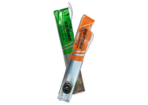
Drop-Type Blast Hole Spacer: The Comprehensive Technical Guide for Free-Fall Activated Air Decking in Mining and Quarry Operations
1. Introduction to Drop-Type Blast Hole Spacers
2. What Is a Drop-Type Blast Hole Spacer?
3. How Drop-type spacers Work: The Free-Fall Activation Mechanism
4. Key Advantages of Drop-Type Spacers
5. Comparison: Drop-Type vs. Push-Type vs. Pull-Up vs. Inflatable Spacers
6. Technical Specifications and Sizing Chart
7. Applications Across Mining, Quarrying, and Civil Engineering
8. Step-by-Step Installation and Operating Procedures
9. Safety Protocols and Regulatory Compliance
10. Economic Analysis: Cost Savings and Return on Investment
11. Troubleshooting and Best Practices
12. Frequently Asked Questions (FAQ)
13. Conclusion and Industry Outlook
In the diverse and demanding world of mining, quarrying, and civil engineering blasting, operational efficiency and simplicity often determine the success of a blast program. Among the various technologies developed to create air decks within explosive charge columns, the drop-type blast hole spacer (also referred to as a free-fall spacer, drop-in blast bag, impact-activated spacer, or gravity-deployed air deck device) stands out for its remarkable simplicity of operation and rapid deployment capability. By leveraging the fundamental force of gravity, this spacer category eliminates complex manual activation procedures, enabling blast crews to achieve effective air decking with minimal training and maximum speed.
The drop-type spacer represents one of the most intuitive approaches to borehole air decking. Unlike push-type spacers that require operators to manipulate valves or buttons at the hole collar, pull-up spacers that demand coordinated traction on activation cords, or purely inflatable systems that rely on external gas sources, the drop-type spacer activates automatically upon reaching the target depth through impact with the bottom of the borehole or a pre-positioned base. This “drop and forget” operational paradigm has made drop-type spacers particularly popular in high-volume production environments where loading cycle time directly impacts daily blast throughput.
The technology has evolved significantly from its origins in simple sandbag and wooden disc deployment to modern engineered systems incorporating chemical inflation, mechanical expansion, and sophisticated impact-triggered mechanisms. Today’s drop-type spacers combine the speed of free-fall deployment with the reliability of automated activation, delivering consistent air deck creation across a wide range of borehole conditions. From Australian open-pit coal operations firing hundreds of holes per shift to African gold mines with deep, narrow stoping holes, the drop-type spacer has proven its value as a practical, cost-effective air decking solution.
This comprehensive guide examines the drop-type blast hole spacer in technical depth, covering its design principles, operational mechanics, comparative advantages, specifications, applications, and economic justification. Whether you are evaluating spacer technologies for a new operation or seeking to optimize existing blast practices, this resource provides the detailed information needed to understand and implement drop-type spacer technology effectively.
A drop-type blast hole spacer is a specialized blast hole accessory designed to create a controlled air deck within a borehole through a free-fall deployment and impact-activated expansion mechanism. The defining characteristic of this spacer category is that activation occurs automatically when the spacer reaches the target depth, typically through impact with the borehole bottom, a pre-positioned base plate, or an internal trigger mechanism that responds to the sudden deceleration of free fall. No manual activation–such as pushing a button, pulling a cord, or connecting an external gas source–is required at the surface.
The functional architecture of a typical drop-type spacer includes:
• Main Body Assembly: A compact, lightweight structure designed to fall freely through the borehole with minimal air resistance. The body may be a folded inflatable bladder, a collapsible mechanical frame, or a self-contained chemical reaction system housed within a protective casing.
• Impact Activation Mechanism: The internal system that triggers expansion or inflation upon sudden deceleration or impact. Common mechanisms include:
– Impact-triggered chemical reaction: A sealed pouch containing reactants (such as sodium bicarbonate and citric acid, or other gas-generating compounds) that ruptures or mixes upon impact, initiating a controlled chemical reaction that produces inflation gas
– Spring-release impact trigger: A mechanical latch held closed during free fall by the absence of compressive force; impact compresses the trigger, releasing pre-tensioned springs that expand the device radially
– Balloon-cord impact release: A compressed elastic balloon held in a folded state by a cord or strap; impact releases the cord, allowing the balloon to expand to its natural shape
– Inertial valve activation: A valve that opens when the spacer’s downward momentum is suddenly arrested, allowing gas from an internal canister to flow into an inflatable bladder
• Deployment Cord / Traction Rope: A lightweight cord attached to the spacer that serves two purposes: (1) controlling the descent rate by providing friction or controlled release, and (2) allowing retrieval if the spacer fails to activate or is dropped into the wrong hole. The cord is typically marked with depth graduations for positioning verification.
• Protective Outer Shell / Scuff Bag: A durable outer layer that protects the internal mechanism from borehole wall abrasion during free fall and contains any chemical reactants or inflation gases.
• Sealing Surface: The expanded portion of the spacer that contacts the borehole wall to create the air deck seal. This may be an inflated bladder, expanded mechanical fins, or an elastic membrane.
The concept of drop-type spacers originated from the simplest form of air decking: lowering objects into boreholes to create physical barriers. Early practitioners used: - Sandbags: Cloth bags filled with sand or gravel, lowered to the desired depth to create a solid platform - Wooden discs: Circular wooden plates lowered on ropes to separate explosive charges - Rock fragments: Large stones or broken drill core pieces dropped into holes to create irregular barriers
These primitive methods were effective in simple, dry, vertical holes but suffered from inconsistent positioning, unreliable sealing, and the labor-intensive requirement for manual retrieval if misplaced.
The first generation of engineered drop-type spacers emerged in the 1970s and 1980s with the development of chemical-reaction inflatable bags. These devices incorporated two separate chemical compartments within a sealed bag. During free fall, an internal barrier kept the reactants separate. Upon impact with the hole bottom, the barrier ruptured, allowing the chemicals to mix and generate gas that inflated the bag. Early designs used vinegar (acetic acid) and sodium bicarbonate, producing carbon dioxide gas. While functional, these first-generation devices had limitations: - Inconsistent reaction rates due to temperature sensitivity - Limited gas volume restricting maximum expansion diameter - Fragile internal barriers that could rupture during rough handling - Residual liquid reactants that could contact explosives
The second generation, developed in the 1990s and 2000s, introduced: - Improved chemical formulations: Dry powder reactants with more consistent reaction rates and greater gas yield per unit mass - Enhanced impact triggers: Mechanical systems that ensured reliable activation only upon significant impact, not from minor bumps during descent - Multi-layer construction: Separate scuff bags and bladder layers to improve durability - Color-coded deployment cords: For easier depth identification
The modern third-generation drop-type spacer, refined from the 2010s onward, features: - Precision-engineered impact triggers: Calibrated to activate only at specific impact forces, preventing false activation from wall contact - High-yield chemical systems: Capable of inflating large-diameter bags to pressures exceeding 0.5 bar - Dual-chamber bladders: Independent gas-tight chambers for redundancy - Temperature-stable formulations: Operating reliably from -20 C to +60 C - Environmentally benign reactants: Non-toxic, non-corrosive chemicals that do not damage explosives or create hazardous fumes
Term | Definition |
Drop-Type Spacer | A blast hole spacer activated by free-fall impact at the target depth, requiring no manual surface activation |
Free-Fall Deployment | The technique of allowing the spacer to descend through the borehole under gravity, optionally controlled by a deployment cord |
Impact Activation | The automatic triggering of the spacer’s expansion mechanism upon sudden deceleration or contact with the borehole bottom |
Chemical Inflation | Gas generation through a controlled chemical reaction initiated by impact, used to expand the spacer bladder |
Deployment Cord | The lightweight cord attached to the spacer for descent control and potential retrieval |
Reaction Time | The interval between impact and full spacer expansion, typically 10-60 seconds for chemical systems |
False Activation | Accidental triggering of the spacer before reaching the target depth, typically from wall contact or rough handling |
Air Deck | The air gap created between explosive charge segments by the expanded spacer |
Charge Column | The vertical or inclined assembly of explosive material within the borehole |
Stemming | The inert material placed above the explosive column to confine detonation gases |
Borehole Diameter | The internal diameter of the drilled hole, typically measured in millimeters or inches |
Deck Height | The vertical distance between explosive charge segments created by the spacer |
Powder Factor | The mass of explosive required to break a unit volume of rock, expressed in kg/m3 or lb/yd3 |
Muck Pile | The broken rock mass produced by a blast |
Bottom Decking | The technique of placing the spacer at the bottom of the borehole to create a bottom air deck |
Middle Decking | The technique of placing the spacer within the charge column to create a mid-column air deck |
The operational sequence of a drop-type spacer can be analyzed in three distinct phases: descent, impact, and expansion.
Phase 1: Descent
During descent, the spacer falls through the borehole under gravity. The dynamics of this phase depend on several factors:
• Initial velocity: If simply dropped from the collar, the spacer starts with zero velocity and accelerates downward. If given an initial push, it may enter the hole with non-zero velocity.
• Gravitational acceleration: The spacer accelerates at approximately 9.8 m/s2 in the absence of air resistance or cord friction.
• Air resistance: The spacer experiences drag proportional to its cross-sectional area, shape, and velocity. Compact, streamlined spacers experience less drag than bulky or irregular shapes.
• Cord friction: If a deployment cord is used, friction between the cord and the borehole wall (or the spacer itself) opposes the motion, reducing acceleration and terminal velocity.
• Wall contact: In rough or irregular boreholes, the spacer may contact the wall, experiencing additional friction and potentially tumbling or rotating.
The descent time for a drop-type spacer in a typical 15-meter borehole ranges from 1.5 to 3.0 seconds, depending on the factors above. This rapid descent is one of the primary operational advantages, as it minimizes the time the loading crew spends on spacer deployment.
Phase 2: Impact
Upon reaching the target depth, the spacer experiences sudden deceleration. The impact dynamics are critical to reliable activation:
• Impact force: The force generated upon contact depends on the spacer’s mass, impact velocity, and the compliance of the contact surface. A typical drop-type spacer impacting at 5-7 m/s generates an impact force of 50-200 N.
• Impact duration: The duration of the impact pulse is typically 1-10 milliseconds. The activation mechanism must respond to this brief pulse.
• Energy absorption: Some spacer designs incorporate energy-absorbing elements (such as compressible foam or elastomeric pads) to protect the internal mechanism from excessive impact forces while still allowing reliable trigger activation.
Phase 3: Expansion
Following successful impact activation, the spacer expands to create the air deck:
• Chemical reaction inflation: For chemically activated spacers, the impact initiates mixing of reactants. The chemical reaction proceeds at a rate determined by the formulation, temperature, and mixing efficiency. Gas generation begins within 1-5 seconds of impact and continues for 10-60 seconds until the bladder reaches full expansion.
• Mechanical expansion: For mechanically activated spacers, impact releases pre-tensioned springs or elastic elements that expand radially. This expansion is nearly instantaneous (0.1-1.0 second).
• Pressure buildup: As the spacer expands, internal pressure increases until the bladder contacts the borehole wall. Continued pressure buildup creates the seal force that holds the spacer in position.
The most common modern drop-type spacer uses a chemical reaction inflation system. The chemistry typically involves:
Primary Reaction System (Acid-Base Gas Generation)
Sodium bicarbonate (NaHCO3) reacts with a weak acid (typically citric acid or acetic acid) to produce carbon dioxide gas:
3 NaHCO3 + C6H8O7 -> Na3C6H5O7 + 3 H2O + 3 CO2
Or with acetic acid:
NaHCO3 + CH3COOH -> CH3COONa + H2O + CO2
Reaction Characteristics
Parameter | Typical Value | Notes |
Gas yield | 0.4-0.6 L CO2 per gram of NaHCO3 | Depends on acid strength and stoichiometry |
Reaction rate | 10-60 seconds to full expansion | Temperature-dependent; faster at higher temperatures |
Heat generation | Endothermic to mildly exothermic | Minimal temperature change; safe for explosive contact |
Residual products | Sodium salts, water | Non-toxic, non-corrosive in standard formulations |
Pressure achieved | 0.3-0.8 bar | Sufficient for seal against borehole wall |
Impact Trigger Design
The impact trigger ensures that reactants mix only upon reaching the target depth:
• Fragile membrane barrier: A thin polymer membrane separates the reactants. Impact ruptures the membrane, allowing mixing.
• Mechanical plunger: A spring-loaded plunger punctures a seal upon impact, releasing one reactant into the other.
• Inertial mixing: The impact causes internal baffles to shift, forcing reactants through mixing channels.
• Crushable capsule: One reactant is encapsulated in a crushable capsule that breaks upon impact.
Some drop-type spacers use purely mechanical expansion without chemical inflation:
Spring-Release Fins - The spacer body contains collapsible metal or polymer fins held retracted by a latch - Impact compresses a trigger element, releasing the latch - Pre-tensioned springs extend the fins radially until they contact the borehole wall - The elastic force of the springs maintains wall contact and seal pressure
Elastic Balloon Expansion - A compressed elastic balloon is held in a folded state by a cord or strap - Impact releases the retention cord - The balloon expands to its natural shape, which is larger than the borehole diameter - Elastic pressure maintains the seal
The drop-type mechanism offers several distinct operational advantages:
1. Simplicity of Operation The operator’s role is reduced to: attach cord, lower to depth, release. No valve manipulation, button pushing, or cord pulling is required. This simplicity: - Minimizes training requirements - Reduces operator error - Enables rapid deployment by less experienced crew members - Allows simultaneous deployment of multiple spacers
2. Speed of Deployment The free-fall descent is the fastest of all spacer deployment methods:
Deployment Method | Typical Time to Depth (15 m hole) | Total Loading Time |
Drop-type | 1.5-3.0 seconds | 8-12 minutes |
Push-type inflatable | 30-90 seconds inflation | 10-15 minutes |
Pull-up | 5-15 seconds lowering + activation | 10-14 minutes |
Rigid spacer | 10-30 seconds lowering | 10-15 minutes |
3. Independence from Surface Conditions Once released, the spacer operates autonomously. This is valuable when: - The hole collar is congested with equipment - Weather conditions make surface operations difficult - Multiple holes are being loaded simultaneously - Remote or automated loading systems are used
4. Consistent Activation Force Unlike manual activation methods where operator strength and technique vary, the impact activation responds to a consistent physical stimulus–gravity and borehole depth. This consistency: - Reduces variability in expansion quality - Improves reliability across different operators - Enables predictable performance in standardized blast designs
The primary advantage of the drop-type spacer is its operational simplicity. The entire deployment procedure can be summarized in three steps:
1. Attach the deployment cord to the spacer
2. Lower the spacer into the borehole to the desired depth
3. Release the spacer and allow it to free-fall to the bottom or target position
No valve selection, no button pushing, no cord pulling, no external equipment connection. This simplicity delivers:
• Minimal training time: New operators can achieve competency within minutes rather than hours or days
• Reduced cognitive load: Operators can focus on other critical aspects of blast loading rather than spacer manipulation
• Lower error rates: The simple procedure has fewer failure modes than complex activation systems
• Language independence: The physical operation transcends language barriers, making drop-type spacers ideal for multinational crews
In high-volume blasting operations, the time required to deploy spacers directly impacts the number of holes loaded per shift and, consequently, the total volume of rock blasted per day. Drop-type spacers offer the fastest deployment cycle:
Operation Step | Drop-Type | Push-Type | Pull-Up | Rigid |
Attach cord | 5 sec | 5 sec | 10 sec | 10 sec |
Lower to depth | 15 sec | 30 sec | 20 sec | 30 sec |
Activate/position | 0 sec (automatic) | 15 sec | 10 sec | 15 sec |
Verify stability | 10 sec | 15 sec | 15 sec | 10 sec |
Total per hole | 30 sec | 65 sec | 55 sec | 65 sec |
Note: Times are approximate for a 15-meter hole with experienced crew.
For a blast pattern of 200 holes, the cumulative time savings from drop-type deployment can exceed 1.5 hours compared to push-type or pull-up systems. This time savings translates directly into: - Increased holes per shift - Reduced equipment idle time - Improved shift productivity metrics - Greater operational flexibility
Open-pit mining operations that fire hundreds of holes per blast benefit disproportionately from drop-type spacers:
• Coal mines: Large blast patterns with 300-500 holes per blast require rapid, consistent spacer deployment
• Iron ore operations: High bench heights (15-25 meters) and large diameters (200-310 mm) are well-suited to drop-type chemical inflation bags
• Quarry operations: High-frequency blasting schedules demand minimal loading time per hole
In these environments, the “drop and move on” capability allows a single operator to deploy spacers across multiple holes while other crew members handle explosive loading and stemming.
Drop-type spacers are particularly effective for bottom decking applications, where the spacer is placed at the bottom of the borehole to create an air deck below the explosive column:
• The free-fall trajectory naturally targets the hole bottom
• Impact activation is guaranteed upon bottom contact
• No depth measurement precision is required–the spacer simply falls to the bottom
• The resulting air deck length equals the distance from the bottom charge to the hole bottom
Bottom decking with drop-type spacers has been shown to: - Improve toe breakage by 20-40% - Reduce sub-drilling requirements by 0.3-0.6 meters - Decrease bottom charge consumption by 15-25% - Reduce ground vibration by 15-30% compared to full bottom charges
Manual activation methods (push, pull, pump) introduce opportunities for human error: - Pushing the wrong button or valve - Pulling the cord at the wrong depth - Forgetting to activate before loading explosives - Activating prematurely during lowering
The drop-type spacer eliminates these errors by making activation an automatic consequence of deployment. The spacer cannot be “forgotten” or “misfired” at the surface–it activates when it reaches the bottom.
The mechanical simplicity of drop-type spacers translates to economic advantages:
• Lower unit cost: Fewer components (no valves, buttons, pumps, or complex actuators) reduce manufacturing cost
• No external equipment: No compressors, gas cylinders, or pumps required
• Reduced labor cost: Faster deployment means less labor time per hole
• Minimal maintenance: No moving parts to service or replace
• High reliability: Simple mechanisms have fewer failure modes
Because activation is automatic and independent of operator technique, drop-type spacers deliver consistent performance regardless of: - Operator experience level - Physical strength or dexterity - Language or communication barriers - Fatigue or shift timing
This consistency is particularly valuable in: - Operations with high crew turnover - Contract blasting services with varying personnel - Remote sites with limited technical support - Automated or semi-automated loading systems
Performance Parameter | Drop-Type Spacer | Push-Type Spacer | Pull-Up Spacer | Pure Inflatable (External Gas) |
Activation method | Automatic impact | Push button/valve | Pull cord | External pump/cylinder |
Operator action required | Release only | Push button at collar | Pull cord at depth | Connect and operate pump |
Activation timing control | None–automatic | Good | Excellent | Good |
Depth precision | Moderate (for bottom decking) | Good | Excellent | Good |
Deployment speed | Excellent (fastest) | Good | Good | Moderate |
Training requirement | Minimal | Moderate | Moderate | Moderate |
False activation risk | Low (impact-calibrated) | Moderate | Very low | Low |
Deep hole suitability | Excellent | Moderate | Excellent | Good |
Multiple spacers per hole | Moderate | Good | Excellent | Good |
Retrievability before activation | Difficult | Yes | Yes | Yes |
Retrievability after activation | No | No | Sometimes (deflate) | Sometimes (deflate) |
Mechanical complexity | Low | Moderate | Low | Moderate to high |
External equipment required | None | None | None | Compressor/pump |
Unit cost | Low | Moderate | Low to moderate | Moderate to high |
Reliability | High | Moderate to high | High | Moderate |
Best application | High-volume, bottom decking, simple operations | Medium-volume, mid-decking | Deep holes, precision, multiple decks | Variable holes, pressure control |
Application Scenario | Recommended Spacer Type | Rationale |
High-volume open-pit production (>200 holes/blast) | Drop-type | Maximum speed, minimal training |
Bottom decking in production holes | Drop-type | Natural bottom targeting, automatic activation |
Shallow holes (<10 m), rapid cycle | Drop-type | Fastest deployment, simple verification |
Precision mid-decking (pre-split, trim) | Pull-up or push-type | Depth verification before activation |
Deep holes (>20 m) with mid-decks | Pull-up | Precise positioning, activation control |
Multiple air decks per hole | Pull-up | Sequential independent activation |
Wet holes with water inflow | Push-type or pull-up | Controlled activation, water displacement |
Variable diameter, irregular walls | Pure inflatable | Adjustable pressure, best conformity |
Underground gassy mines | Drop-type or pull-up | Simple mechanism, minimal ignition risk |
Automated loading systems | Drop-type | Compatible with robotic release |
Remote sites, limited technical support | Drop-type | No external equipment, minimal maintenance |
Cost Component | Drop-Type Spacer | Push-Type Spacer | Pull-Up Spacer | Pure Inflatable |
Spacer unit cost | $6-$15 | $10-$25 | $8-$20 | $15-$40 |
External equipment | $0 | $0 | $0 | $500-$2,000 (pump) |
Loading labor | $2-$6 | $4-$10 | $3-$8 | $8-$15 |
Training cost (amortized) | Very low | Low | Low | Moderate |
Failure/replacement rate | 3-8% | 5-10% | 2-5% | 5-10% |
Explosive savings | 10-30% | 15-30% | 15-30% | 15-30% |
Secondary breakage reduction | 15-35% | 20-40% | 20-40% | 20-40% |
Net cost per hole | -$8 to -$25 | -$8 to -$22 | -$10 to -$27 | -$5 to -$20 |
Note: Negative values indicate net savings after accounting for spacer cost.
Drop-type blast hole spacers are manufactured in a range of sizes to accommodate common borehole diameters. The following specifications represent industry-standard product lines:
Specification Parameter | Standard Range | Typical Values | Notes |
Borehole diameter compatibility | 75 mm - 380 mm | 90, 115, 150, 165, 200, 250, 310 mm | Custom sizes available |
Collapsed spacer outer diameter | 30 mm - 70 mm | 40, 50, 60 mm | Must pass through borehole without hanging |
Collapsed spacer length | 400 mm - 600 mm | 500, 600 mm | Compact for easy handling and storage |
Expanded diameter (activated) | 80 mm - 420 mm | Matches borehole diameter + 10-20 mm | Oversized for wall contact and seal |
Effective air gap length | 1.0 m - 3.0 m | 1.5, 2.0 m | Adjustable via cord positioning for mid-decks |
Unit weight (collapsed) | 0.1 kg - 0.5 kg | 0.2, 0.3, 0.4 kg | Lightweight for easy manual handling |
Bladder material (inflatable types) | Synthetic elastomer | EPDM, nitrile, polymer blend | Gas-tight, abrasion-resistant |
Scuff bag material | Woven polymer fabric | HDPE, PP, nylon blend | High-visibility, tear-resistant |
Deployment cord length | 15 m - 30 m | 20, 25 m | Marked with depth graduations every 0.5 m |
Deployment cord breaking strength | 100 kg - 300 kg | 200 kg | Sufficient for retrieval if needed |
Operating temperature range | -20 C to +60 C | Standard grade | High/low temperature variants available |
Maximum inflation pressure | 0.3 - 0.8 bar | 0.5 bar | Pressure relief prevents over-inflation |
Reaction time (impact to full expansion) | 10 - 60 seconds | 30 seconds | Temperature-dependent |
Gas source | Internal chemical reaction | Self-contained | No external equipment required |
Shelf life (unactivated) | 1 - 3 years | 2 years | Store in cool, dry conditions |
Parameter | Typical Value | Notes |
Impact force required for activation | 30 - 150 N | Calibrated for typical free-fall velocities |
Impact velocity at activation | 3 - 8 m/s | Depends on hole depth and descent conditions |
False activation resistance | >50 N side load | Won’t activate from wall contact alone |
Time from impact to seal establishment | 15 - 90 seconds | Chemical reaction rate determines speed |
Seal pressure at wall contact | 0.2 - 0.6 bar | Sufficient to hold position under load |
Maximum hold load (axial) | 50 - 200 kg | Weight of explosive column spacer can support |
Component | Material | Properties |
Inner bladder | Multi-layer elastomeric film | Gas-tight, flexible, puncture-resistant |
Outer scuff bag | Woven HDPE or PP | Abrasion-resistant, UV-stable, high-visibility |
Chemical reactants | Sodium bicarbonate + citric acid (or equivalent) | Non-toxic, non-flammable, environmentally benign |
Reaction chamber | Sealed polymer pouch | Ruptures reliably upon impact |
Deployment cord | Braided polyester or polypropylene | Low stretch, rot-resistant, marked |
Impact trigger | Engineering polymer or thin metal | Calibrated rupture strength |
Borehole Diameter (mm) | Borehole Diameter (in) | Recommended Spacer Model | Expanded Diameter Range (mm) | Typical Application |
76-90 | 3.0-3.5 | DT-90 | 90-110 | Small diameter, underground development |
90-115 | 3.5-4.5 | DT-115 | 115-140 | Medium diameter, production drilling |
115-150 | 4.5-5.9 | DT-150 | 150-190 | Standard production, quarry blasting |
150-165 | 5.9-6.5 | DT-165 | 165-200 | Medium-large production holes |
165-200 | 6.5-7.9 | DT-200 | 200-240 | Large diameter, open-pit production |
200-250 | 7.9-9.8 | DT-250 | 250-300 | Large production, cast blasting |
250-310 | 9.8-12.2 | DT-310 | 310-370 | Very large diameter, bulk explosive loading |
310-380 | 12.2-15.0 | DT-380 | 380-420 | Specialized large-hole applications |
Open-pit coal mines represent one of the largest markets for drop-type spacers due to:
• High hole counts: Blast patterns with 300-600 holes per blast require rapid deployment
• Consistent hole conditions: Relatively uniform, dry, vertical holes ideal for free-fall deployment
• Bottom decking preference: Coal seams often benefit from bottom air decks to improve floor breakage and reduce overbreak into overburden
• Cost sensitivity: Tight margins in coal mining favor low-cost, high-efficiency spacer solutions
Typical applications include: - Production blasting on 10-20 meter benches - Cast blasting for overburden removal - Pre-splitting for highwall stability
Iron ore, copper, gold, and other metal mines utilize drop-type spacers for:
Iron Ore Operations - Large-diameter holes (200-310 mm) with high powder factors - Deep benches (15-25 meters) where drop-type speed is critical - Hard rock conditions where bottom decking improves toe breakage
Copper/Gold Porphyry Deposits - Medium to large diameter holes (150-250 mm) - Variable rock hardness requiring flexible deck placement - High-altitude operations where simple mechanisms are preferred
Quarries producing aggregate for construction benefit from drop-type spacers through:
• High-frequency blasting: Daily or multi-daily blasts require efficient loading
• Simple operations: Many quarries operate with small crews; minimal training is advantageous
• Bottom decking for crusher feed: Improved fragmentation uniformity
• Vibration control near boundaries: Air decking reduces ground vibration for compliance
While less common than in surface operations, drop-type spacers find underground application in:
Development Face Blasting - Vertical or near-vertical cut holes where free-fall deployment is feasible - Simple, rapid loading in confined spaces - Bottom decking to improve floor level and reduce overbreak
Production Stoping - Downward-angled blast holes in sublevel stoping - Slot raise development - Where simple, reliable mechanisms are preferred over complex systems
Road and Highway Construction - Rock excavation for cuts and fills - Rapid cycle times to maintain construction schedules - Simple deployment in variable conditions
Foundation and Trench Blasting - Shallow holes where drop-type speed is maximized - Consistent bottom levels for foundation preparation
Demolition and Secondary Breaking - Small-diameter holes in concrete or rock demolition - Quick deployment in time-sensitive operations
1. Borehole Inspection - Measure and record depth, diameter, and inclination - Verify hole is free of obstructions, water, or excessive debris - Check for wall stability and absence of collapsed sections - Ensure hole is dry or that water level is known (drop-type spacers are generally designed for dry holes)
2. Spacer Selection and Verification - Select spacer size matching borehole diameter - Inspect for packaging integrity–do not use if packaging is damaged or punctured - Verify expiration date is within acceptable range - Check deployment cord is securely attached and depth markings are legible - Do not remove protective packaging or tape until ready to deploy
3. Blast Design Review - Confirm target deck height or bottom decking requirement - For mid-decking, calculate the cord length needed to position the spacer at the correct elevation - Verify deck height is within explosive air gap sensitivity limits
Step 1: Prepare the Spacer - Remove the spacer from its outer packaging - Keep any inner protective wrapping intact until the moment of deployment - Verify the deployment cord is securely attached to the spacer body - Do not drop, crush, or puncture the spacer
Step 2: Attach the Deployment Cord - Tie the deployment cord to the spacer’s attachment point using a secure knot - Verify the cord length is sufficient to reach the hole bottom with surplus for handling - For mid-decking, mark the cord at the target depth (e.g., 10 meters for a 15-meter hole with 5-meter bottom deck)
Step 3: Lower the Spacer - Hold the spacer over the borehole collar - Allow the spacer to descend into the hole, feeding the cord through your hands - For controlled descent, maintain light friction on the cord to slow the fall - For maximum speed, release the spacer and allow free fall - Monitor the cord markings to track descent depth
Step 4: Impact and Activation - The spacer falls to the hole bottom under gravity - Impact triggers the internal mechanism (chemical mixing or mechanical release) - Listen for sounds of inflation or expansion (hissing, popping, or mechanical clicking) - Wait for the reaction to complete (typically 15-60 seconds)
Step 5: Verify Activation and Stability - Gently pull the deployment cord to verify the spacer has expanded and gripped the wall - If the cord comes up freely, the spacer may not have activated–do not load explosives - If the cord is taut and the spacer resists upward movement, activation is confirmed - For chemical inflation, wait the full reaction time before loading
Step 6: Load Explosive Charge - Once the spacer is confirmed stable, load the explosive charge above the spacer - For bottom decking, load the main charge column from the spacer upward - For mid-decking, load the lower charge first, then the spacer, then the upper charge
Step 7: Apply Stemming - Fill the remaining borehole volume with stemming material - Compact adequately for confinement
Step 8: Connect Initiation System - Connect the detonator to the surface initiation network - Verify connections and sequencing - Conduct final pattern inspection
For mid-column air decks, a modified procedure is required:
1. Load the bottom explosive charge to the designed depth
2. Lower the drop-type spacer to the target elevation using the deployment cord
3. Position the spacer at the correct depth by holding the cord at the marked position
4. Release the spacer and allow it to fall the remaining short distance to the lower charge surface
5. The impact with the lower charge or a pre-positioned base triggers activation
6. Verify activation and stability
7. Load the upper explosive charge
Note: Mid-decking with drop-type spacers requires careful depth control. The spacer must be positioned accurately before the final short drop that triggers activation. Some operators use a temporary stop or cord clamp to hold the spacer at the exact elevation before release.
Check Item | Verification Method | Acceptance Criteria |
Spacer size matches hole diameter | Visual comparison, gauge | Expanded diameter > hole diameter |
Spacer packaging intact | Visual inspection | No punctures, tears, or damage |
Expiration date valid | Check printed date | Within manufacturer’s specified shelf life |
Deployment cord secure | Tug test | Cord supports spacer weight without slipping |
Depth marking legible | Visual inspection | Clear at 0.5 m intervals |
Spacer reaches target depth | Cord marking | At or near hole bottom for bottom decking |
Activation confirmed | Sound + tug test | Hissing/mechanical sound; cord resists pull |
Spacer stable under load | Wait + tug test | No displacement after full reaction time |
Explosive loaded correctly | Depth measurement | Charge at design elevation |
Stemming adequate | Visual + depth measure | Per blast design |
• Store in original packaging in a cool, dry, well-ventilated magazine
• Keep away from direct sunlight, heat sources, and open flames
• Maximum storage temperature: 40 C (104 F)
• Separate from detonators and initiation devices
• Do not store with acids, bases, or other chemicals that could react with spacer contents
• Inspect quarterly for packaging integrity and expiration dates
• Do not drop, crush, or puncture stored spacers
• Maintain inventory records with lot numbers and expiration dates
• Only trained and certified personnel should handle and deploy drop-type spacers
• Wear appropriate PPE: hard hats, safety glasses, hearing protection, high-visibility clothing, steel-toe boots
• Maintain clear communication between crew members
• Do not stand directly over the borehole during spacer release
• Ensure the deployment cord does not snag on equipment or clothing during lowering
• If a spacer fails to activate, do not attempt to re-impact or strike it
• Do not retrieve an activated spacer–once expanded, it is single-use
• In windy conditions, secure the deployment cord to prevent spacer drift
Underground Gassy Mines - Spacer materials must be non-metallic, non-sparking, and antistatic - Chemical reactants must be non-flammable and non-toxic - Fume characteristics must be tested and approved for the mine’s gas classification - Documented risk assessments should address chemical reaction products
Surface Mines and Quarries - Compliance with local blasting codes and environmental regulations - Vibration monitoring may be required when implementing new air decking techniques - Air overpressure and flyrock control plans
Transportation - Drop-type spacers with chemical reactants may be classified as dangerous goods for transportation - Follow applicable UN classification, ADR, DOT regulations - Proper labeling, packaging, and documentation required
Hazard | Risk Description | Mitigation Strategy |
Premature activation | Rough handling ruptures internal barrier before deployment | Handle gently; inspect packaging; reject damaged units |
Failed activation | Insufficient impact force; defective trigger | Verify hole depth adequate for impact velocity; replace if failed |
False activation from wall contact | Rough borehole wall triggers mechanism during descent | Lower slowly in rough holes; select impact-calibrated design |
Chemical exposure | Ruptured spacer releases reactants | Wear gloves; wash hands after handling; do not ingest |
Deployment cord breakage | Excessive load; damaged cord | Inspect cord before use; use rated breaking strength |
Spacer hang-up | Hole obstruction prevents free fall to bottom | Inspect hole before loading; clear obstructions |
Gas accumulation | CO2 or other gases in confined space | Ensure ventilation; gases are non-toxic but can displace oxygen |
Static electricity | Static buildup on polymer surfaces | Use antistatic materials; ground equipment |
Cost/Benefit Item | Conventional Continuous Charge | With Drop-Type Spacer | Variance |
Explosive quantity | 100% baseline | 70-85% of baseline | -15% to -30% |
Explosive cost | $X per hole | $0.70X - $0.85X | -$0.15X to -$0.30X |
Spacer unit cost | $0 | $6-$15 | +$6 to +$15 |
Loading labor | Baseline | Reduced (faster deployment) | -10% to -20% |
Loading labor cost | $Y per hole | $0.80Y - $0.90Y | -$0.20Y to -$0.10Y |
Secondary breakage | $Z per hole | $0.50Z - $0.70Z | -$0.30Z to -$0.50Z |
Drilling (sub-drill reduction) | Baseline depth | -0.3 to -0.5 m | -$5 to -$15 per hole |
Training cost | Baseline | Reduced (minimal training) | -$0.50 to -$2 per hole |
Assumptions: - 300 blast holes per blast - 4 blasts per week - 150 weeks per year - Average explosive consumption: 40 kg/hole at $2.00/kg - Average hole depth: 15 m - Labor rate: $50/hour; loading time: 8 minutes/hole with drop-type vs. 12 minutes baseline
Benefit Category | Calculation | Annual Savings |
Explosive reduction (20%) | 300 x 4 x 50 x 40 kg x 20% x $2.00 | $960,000 |
Sub-drill reduction (0.4 m) | 300 x 4 x 50 x 0.4 m x $50/m | $1,200,000 |
Loading labor efficiency (33% time reduction) | 300 x 4 x 50 x 4 min x $50/60 min | $200,000 |
Secondary breakage reduction (30%) | $400/blast x 4 x 50 x 30% | $24,000 |
Training cost reduction | $5,000/year (simplified) | $5,000 |
Total gross annual benefits | $2,389,000 | |
Less: Spacer costs | 300 x 4 x 50 x $12 average | -$720,000 |
Net annual savings | $1,669,000 |
Implementation Phase | Timeline | Cumulative Investment | Cumulative Savings | Net Position |
Trial phase | Months 1-2 | $15,000 | $0 | -$15,000 |
Initial rollout | Months 3-6 | $100,000 | $400,000 | +$300,000 |
Full implementation | Months 7-12 | $720,000 | $1,194,500 | +$474,500 |
Year 1 total | 12 months | $720,000 | $1,669,000 | +$949,000 |
Year 2 total | 24 months | $1,440,000 | $3,338,000 | +$1,898,000 |
Issue | Probable Cause | Corrective Action | Preventive Measure |
Spacer fails to activate | Insufficient impact; defective trigger; depleted reactants | Replace spacer; verify hole depth adequate for impact | Inspect packaging; ensure adequate hole depth |
Spacer activates during handling | Rough handling ruptures internal barrier | Discard spacer; use replacement | Handle gently; reject damaged packaging |
Spacer inflates but doesn’t seal | Undersized for hole; wall too irregular | Replace with larger size | Measure hole diameter; select correct size |
Spacer hangs up during descent | Hole obstruction; collapsed section | Retrieve if possible; clear obstruction | Inspect hole before loading |
Deployment cord breaks | Excessive load; damaged cord | Use retrieval tool if possible | Inspect cord before use |
Activation too slow in cold weather | Low temperature slows chemical reaction | Allow extended reaction time | Store spacers at ambient temperature before use |
Spacer position incorrect (mid-deck) | Depth marking misread; cord slippage | Replace spacer; re-verify depth | Independent depth verification |
Residual liquid from chemical reaction | Excess reactant liquid not absorbed | Allow drainage time; use absorbent spacer design | Select dry-formulation spacers |
Storage and Handling - Rotate inventory to use oldest stock first - Avoid temperature extremes during storage and transport - Do not stack heavy objects on spacer packages - Keep spacers dry until deployment
Hole Preparation - Clean hole collars of loose material - Verify hole is dry or measure water depth - Mark collar with hole number and target depth
Deployment Technique - Lower smoothly without sudden jerks - Maintain light cord tension for controlled descent - Release cleanly without snagging - Step back from hole collar after release
Post-Deployment Verification - Wait full reaction time before loading explosives - Verify activation by cord tug test - Listen for inflation sounds - Do not rush the loading process
Q1: What is the difference between a drop-type spacer and other spacer types?
A: A drop-type spacer is activated automatically by free-fall impact at the target depth, requiring no manual surface activation. Push-type spacers require pressing a button or valve at the collar. Pull-up spacers require pulling a cord to activate. Pure inflatable spacers require external gas sources. The drop-type’s automatic activation makes it the simplest and fastest to deploy, ideal for high-volume operations and bottom decking.
Q2: Can drop-type spacers be used in all borehole diameters?
A: Drop-type spacers are manufactured for borehole diameters from approximately 75 mm to 380 mm. It is essential to select the spacer model whose expanded diameter range matches or slightly exceeds the target borehole diameter. Using an undersized spacer will result in seal failure, while an oversized spacer may not fit through the hole. Custom sizes can often be manufactured for specialized applications.
Q3: How do I control the depth of a drop-type spacer for mid-decking?
A: For mid-decking (creating an air deck in the middle of the charge column), use the deployment cord to lower the spacer to the target elevation, then release it to fall the remaining short distance onto the lower explosive charge or a pre-positioned base. The cord markings help verify depth. Some operators use a temporary cord clamp or stop to hold the spacer at the exact elevation before the final release. Note that bottom decking (falling to the hole bottom) is the most common and reliable application for drop-type spacers.
Q4: What happens if a drop-type spacer fails to activate?
A: If a spacer fails to activate upon impact, do not attempt to strike or re-impact it, as this could damage the mechanism or create a safety hazard. Attempt to retrieve it using the deployment cord if possible. If retrieval is not possible, consult the blast engineer to determine if the hole can be loaded with a modified design (continuous charge) or must be abandoned. Always have spare spacers available for replacement.
Q5: Can drop-type spacers be retrieved after deployment?
A: No. Once activated, drop-type spacers are permanently expanded and cannot be retrieved. The deployment cord can be cut or left in place. Before activation, retrieval is possible by pulling the cord, but this risks accidental activation if the spacer contacts the wall or bottom during retrieval.
Q6: Are drop-type spacers safe for use in underground gassy coal mines?
A: Yes, provided the spacer is constructed from non-metallic, non-sparking, antistatic materials and uses non-flammable, non-toxic chemical reactants. The simple mechanism minimizes ignition risk. However, the fume characteristics of the chemical reaction products must be tested and approved for the specific mine’s gas classification. Always verify local regulatory requirements.
Q7: How do temperature extremes affect drop-type spacer performance?
A: Chemical reaction rates are temperature-dependent. In cold conditions (below 0 C), reaction times may double or triple. In hot conditions (above 40 C), reactions may proceed faster and with higher pressure. Store spacers at ambient temperature before use. For extreme conditions, select temperature-rated formulations. Never use spacers that have been frozen, as ice crystals may rupture internal barriers.
Q8: Can drop-type spacers be used in wet or water-filled holes?
A: Standard drop-type spacers are designed for dry holes. Water can interfere with the chemical reaction, prevent proper expansion, or wash away reactants. For wet holes, specialized water-resistant drop-type spacers or alternative technologies (Water Hole Spacers, weighted rigid spacers) should be used. If a hole has minor water at the bottom, rapid deployment may allow activation before water interferes, but this is not recommended as standard practice.
Q9: What is the typical shelf life of an unactivated drop-type spacer?
A: Unactivated drop-type spacers typically have a shelf life of 1-3 years when stored in original packaging under recommended conditions (cool, dry, away from direct sunlight). Always check the expiration date printed on the packaging. Expired spacers may have degraded reactants or weakened internal barriers, leading to activation failure or premature activation.
Q10: Can multiple drop-type spacers be used in a single borehole?
A: Yes, but with limitations. Multiple drop-type spacers can be deployed sequentially in a single borehole to create multiple air decks. However, because each spacer activates automatically upon impact, precise depth control for upper decks is challenging. The lower spacer must be fully activated and stable before the upper spacer is deployed. For multiple precise mid-decks, pull-up or push-type spacers with independent activation control are generally preferred.
Q11: How do drop-type spacers affect blast vibration?
A: Air decking with drop-type spacers typically reduces ground vibration by 15-30% for bottom decking and 30-75% for mid-decking compared to continuous charges of equivalent total explosive weight. The air deck moderates initial shock intensity and distributes energy release. The exact reduction depends on deck height, explosive type, and geological conditions.
Q12: What training is required for crews using drop-type spacers?
A: Minimal training is required–typically 15-30 minutes of instruction covering: storage and handling; inspection before use; attachment of deployment cord; lowering and release technique; activation verification; and safety protocols. Most operators achieve competency after deploying 2-3 spacers under supervision. This minimal training requirement is one of the key economic advantages of drop-type spacers.
The drop-type blast hole spacer represents the epitome of practical, field-focused blasting engineering–delivering effective air decking through the simplest possible mechanism: gravity and impact. By eliminating manual activation steps, external equipment, and complex training requirements, this technology enables mining and quarrying operations to achieve the proven benefits of air decking (explosive savings, improved fragmentation, reduced blast side effects) with maximum operational efficiency and minimum cost.
The technology’s core strengths–speed, simplicity, reliability, and cost efficiency–make it the preferred choice for high-volume production environments, bottom decking applications, and operations where crew training resources are limited. The automatic activation mechanism ensures consistent performance across operators, shifts, and seasons, reducing the variability that can compromise blast quality.
For operations currently using continuous explosive columns, rigid spacers, or more complex inflatable systems, the transition to drop-type spacers requires minimal investment and delivers immediate returns. The combination of reduced explosive consumption, faster loading cycles, lower training costs, and improved blast outcomes creates a compelling economic case that typically pays back within the first month of implementation.
Looking to the future, drop-type spacer technology is evolving along several paths:
Enhanced Chemical Formulations Research is advancing toward reactants with faster, more consistent reaction rates across temperature extremes, greater gas yield per unit mass, and even more environmentally benign reaction products.
Improved Impact Triggers Next-generation triggers will offer calibrated activation forces that prevent false activation from wall contact while ensuring reliable activation at the hole bottom, even in soft or muddy conditions.
Smart Packaging Integrated temperature indicators, humidity sensors, and expiration alerts will help operators ensure spacer reliability before deployment.
Biodegradable Materials Development of spacer components that degrade harmlessly in the post-blast environment will address growing environmental concerns.
Integration with Automated Systems Drop-type spacers are inherently compatible with automated loading systems, as the simple release mechanism can be easily mechanized for robotic deployment.
For blast engineers, mine managers, and quarry operators seeking to optimize air decking practices, the drop-type blast hole spacer offers a proven, practical, and profitable solution. Its combination of mechanical simplicity, operational speed, and reliable performance embodies the kind of field-smart engineering that transforms good blast designs into consistently excellent blasting outcomes.
• Air Decking Fundamentals: Principles of Explosive Energy Distribution in Boreholes
• Blast Fragmentation Optimization Through Controlled Air Gap Design
• Ground Vibration Reduction Techniques in Surface and Underground Blasting
• Comparative Analysis of Blast Hole Spacer Activation Mechanisms
• Powder Factor Optimization and Economic Blasting in Open-Pit Mining
• Safety Standards for Chemical-Reaction Devices in Mining Environments
• Controlled Blasting Methods: Pre-Splitting, Cushion Blasting, and Trim Blasting
• The Role of Bottom Decking in Toe Breakage and Floor Control
• Best Practices for High-Volume Production Blasting
• Training and Competency Standards for Blast Crews Using Drop-Type Spacers
This guide is intended for informational and educational purposes. It does not replace site-specific blast design, safety protocols, or regulatory compliance requirements. Always consult qualified blasting professionals, explosive manufacturers, and regulatory authorities before implementing new blasting technologies or modifying existing practices.
This website uses cookies to ensure you get the best experience on our website.
 中文
中文


 WhatsApp
 Phone
Phone